This thread has been locked.

If you have a related question, please click the "Ask a related question" button in the top right corner. The newly created question will be automatically linked to this question.

TPS65251 not working

Other Parts Discussed in Thread: TPS65251

Hello.

We are developing a new application where the TPS65251 is used to generate respectively 1.8V, 3.3V and 1.2V using DC/DC 1, 2 and 3. The product is powered at 12V.

While 1.8V and 1.2V (DCDC number 1 and 3) seem to work good by quick tests, the 3.3V section has big problems; 3 of 5 prototipe show high consumptions,

even if the PSU outputs are disconnected, so no load at all. All the consumption goes to heat, the IC becomes very hot.

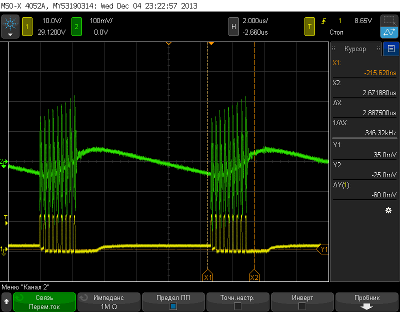
The 3.3V DCDC doesn't regulate at all, and continues to start-stop, so output is something similar to a square wave, with on phase at around 1.5V output and off phase at 0V.

The frequency of this strange behaviour is around 25Hz. Also input power consuption is pulsed in this way.

The strange thing is that if I disconnect completely the inductor of the 3.3V DCDC, the wave on the LX2 doesn't change, neither consumption.

Also the 1.8V and 1.2V DCDC seem to continue to turn on-off in the same way of the 3.3V DCDC, but they regulate (output voltage is correct, but with a lot of ripple).

If I disable 3.3V DCDC using EN pin, the other two DCDC work good and consuption drops.

I think that these chips have strange problems, maybe they are broken.Problem is the very high incidence of defect parts...

 I would try to replace these ICs, but samples are out now...

Any suggestion?


  • Andrea,

    Engineering operations manager for this product, can you send me the 3 IC's that are having this problem? You can send it to the address below.  Also please send me your address, i have some units, i can ship to you. Let me know.

    Texas Instruments Inc.

    13560 N. Central Expressway

    MS:3744

    Dallas, TX 75243

    USA.

    Thanks

    Vash Narula


  • Hello Vash,

    I'm organizing to dismount the components and to send you the broken pieces.

    In the meantime, after three days of perfect operation, the fourth piece of five broke down... :(

    I was trying a sequence of turn-on and turn-off operations on a product, with period of some seconds, to simulate user operation. Suddenly the PSU failed, now I have the same behaviour as the other three.

    We have a severe problem here!  I don't understand if the fact could be caused by something wrong in the project or if it depends on something happening inside the chip.

    I see another strange behaviour comparing signals on LX1 and LX2 on a broken piece: while during the off-stage the LX1 pin (still working DCDC at 1.8V) goes to the same voltage as output (internal transistor should be open and diode not conducting, that's correct), on LX2 (broken DCDC at 3.3V) the voltage goes to 0V (internal diode shorted?).

    Please help me to understand if the problem could be related to the particular application or if there's a criticity on the TPS65251, and in case how to avoid it.

    Did you ever see similar cases on this component? I ask because we are going to a massive use of this PSU on many new products, so we need to be absolutely sure.

    I wait for some news (hope good).

    Thanks

    Andrea


  • Andrea,

    Can you send me your email address. Mine is vash@ti.com. We can discuss through email, i have some points.

    thanks

    Vash

  • Hello!

    I have similar problem with TPS65251RHA.

    I am using TPS65251RHA to generate respectively 1.5V, 1.2V and 1.8V using DC/DC 1, 2 and 3. The board is powered at 9V to 15V. I have tested it at 12V.

    All components are like in evalution board. (with the exception of resistor dividers for feedback )

    At first all voltages and power consumption were ok.

    I was trying a sequence of turn-on and turn-off operations on a board without any load, with period of some seconds. Suddenly power consumption grews up and IC became very hot. It was error in 1.2V line.  Voltage ripple increased in this line. Look oscillogram: (green - output voltage, yellow - signal on LX2)

    I measured resistance between LX2 and GND, it was about 14 ohms. Resistance between LX1 or LX3 was greater 20kohms

    And now all three channel have failed. And this problem occurs on other boards.

    What is wrong? What must i do to solve this problem? 

    We are going to use this PSU in our new products and it is very important to solve this problem!

    Thanks in advance

    Best regards,

    Polukhin Alexander.

    P.S. Sorry for my bad english

  • Hi

    This is Wentao from TI china  Beijing R&D center. 

     Nice to meet you.

    You can contact me if you have any issue in 251. I saw you weretrying a sequence of turn-on and turn-off operations on a board without any load. And I found that , your Switching frequency is nearly 5MHz from the waveform, Am I right? It seems very strange.

    Could you please tell me the detail of the  operations and you SCH? You can also send the detail to my Email: w-xie@ti.com.

    Thank you very much!