


Hi.
This is about buck-boost IC TPS63802, about the input and output capacitors.
This is the disposition and values of capacitors of a layout that the design and layout is in progress, below.
I will show before, the capacitors that we currently use, that could be used without creating additional capacitor items.
- Capacitor ceramic SMD, 47uF, +-20%, 10V, 0805, X5R, GRM21BR61A476ME15L (Murata)
- Capacitor ceramic SMD, 10uF, +-20%, 10V, 0402, X5R, CL05A106MP8NUB8 (Samsung)
- Capacitor ceramic SMD, 4.7uF, +-20%, 10V, 0402, X5R, CL05A475MP5NRNC (Samsung)
- Capacitor ceramic SMD, 1uF, +-10%, 25V, 0402, X5R, GRM155R61E105KA12D (Murata)
- Capacitor ceramic SMD, 100nF, +-10%, 50V, 0402, X7R, Low ESL, C1005X7R1H104K050BB (TDK)
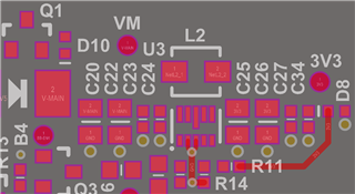
In the picture above. At input, C20 and C22 are 47uF, C23 is 10uF and C24 is 100nF. At output, C25 and C26 are 47uF, C27 is 10uF and C34 is 100nF.
I did this this way, placing the smaller capacitors closer to the input and further away at the output because my mentor said that the smaller capacitors always goes placed closer to the device that will receive the energy.
In this case, Vout is 3.3V and Vin range would be from 2.7V to 4.5V.
Below is another layout I did with TPS63802, the PCB was not produced yet, I will make the drawing of the copper in a similar way to this, using solid polygons for input, output and ground, vias underneath the IC.
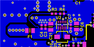
These boards have 8 layers with 3 ground planes, being one ground plane right below/above the top and bottom layer.
What would be the TI engineers comments? How about these combinations from higher to lower capacitances at the inputs? I wanted a way to reduce emissions, if possible.
Would it be better to connect the 47uF capacitors directly close to the inputs, removing the smaller capacitors?
I saw in the following link: www.murata.com/.../productdetail
About the 47uF, that at about 2MHz, its impedance is about 9mOhm.
And at the following link: product.tdk.com/.../info
About the 100nF, that at about 2MHz its impedance is about 880mOhm.
And in the following link: product.samsungsem.com/.../CL05A106MP8NUB.do
About the 10uF, that at abut 2MHz its impedance is about 7mOhm.
Regards,
Jeferson Pehls.
