Hi,
I have a question on design. The continuous power is 300W but the peak power is estimated to be about 700W. With an aim to avoid the converter going into burst mode, how can I go about with the design?
Thanks.
This thread has been locked.
If you have a related question, please click the "Ask a related question" button in the top right corner. The newly created question will be automatically linked to this question.
Hi,
I have a question on design. The continuous power is 300W but the peak power is estimated to be about 700W. With an aim to avoid the converter going into burst mode, how can I go about with the design?
Thanks.
Hi Gautham,
Please use the design calculator (https://www.ti.com/lit/zip/sluc675) for your LLC design for 700W.
VCR pin capacitors and BW and LL/SS pin resistors can be tuned to avoid the controller to operate at the burst mode when the load is at 300W.
Please feel free to share your design before you start working on your schematics.
Regards
Manikanta P
You can share through e2e direct message. I will send you a connection request.
Regards
Manikanta P
Hi gautham,
In your design calculator, I observed that the LLC tank max gain is not able to match the required gain.
You need to adjust the LLC parameters to make sure both max and min gain are met.
Please see the design example given in the app note (from page 21) and adjust the parameters accordingly.
Designing an LLC Resonant Half-Bridge Power Converter Article
Regards
Manikanta P
HI Manikanta,
Thank you for pointing it out. I did readjust the values could you please take a look again?
Thanks,
Gautham Venkat
Hi Gautham,
I have reviewed the new design calculator. It looks okay.
I am closing this thread. please feel free tore open this thread if you have any issues.
Regards
Manikanta P
Hi Manikanta,
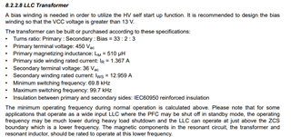
Thank you for the help. I have another question, The values of the primary terminal voltage and the secondary terminal voltage shown here. are they calculated with some headroom? How is the value of 450Vac and 36Vac calculated?

Hi,
There is a typo here. these are pk values not rms. These values (450V peak,36V peak) allow margin for transformer design. 450V pk is because the input voltage of LLC doesn’t beyond 450V because PFC capacitor is 450V rating. 36V pk is because of Vo=12V and voltage stress of 2nd winding is 24V, and 36V pk is 1.5*24V for 50% margin.
Regards
Manikanta P