This thread has been locked.

If you have a related question, please click the "Ask a related question" button in the top right corner. The newly created question will be automatically linked to this question.

LM5177: Current control from MCU and IMONOUT polarity

Part Number: LM5177


Dear TI experts

What is the best way to implement current control of LM5177 with a signal (PWM or DAC) coming from MCU?

We need to control the current from the battery between -15A (max charging current) and +15A (max discharge current).

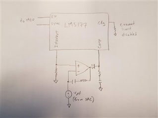
The best solution I have come up with is the one drawn in the picture below. But I realized that maybe IMONOUT only measures current in the positive direction (V_IMONOUT = V_ISNSP − V_ISNSN × gm × R_IMONOUT). If SYNC pin is low at startup, will this also change the polarity/direction of the IMONOUT (in addition to changing the polarity of the current limiter)?

Do you have any other solutions for controlling the current in both positive and negative direction?

Thanks,

Ole

  • HI Ole,

    thank you for using the E2E forum.

    Your idea is very close to another option.

    Use the IMON feature - as you intended. The IMON has an internal current source which can source and sink current. So, if you add an external Voltage divider between a known voltage (Reference), the IMONOUT and GND, you can measure the current both direction as a voltage. 

    To regulate you can use the ATRK input to adjust the output voltage so that you get the required current.

    All together:

    - IMONOUT gives you a voltage signal representing the current.

    - this is measured with an ADC

    - some logic and a digital filter generate the ATRK signal which adjusts the output voltage.

    - you can of course also inject the signal at the COMP pin, but you need to control in both directions.

    Note: SYNC level at startup configures the ILimiter not the IMonitor.

    Note 2: i am just working on an application report show that (only for one direction) but it is currently in draft and i hope to release it till end of the year.

    Best regards,

     Stefan

  • Hi Stefan,

    Thank you for your detailed answer.

    I didn't know that the current source could sink current, that is good news.

    If I calculated correctly then a voltage divider with 2x 66kohm resistors from 3.3V to gnd with middle point connected to IMONOUT, will generate a voltage from 0-3.3V corresponding to -50mV-50mV over Rsns resistor (-50uA-50uA sink/source current).

    I thought using a regulator in series with the voltage regulator and especially using MCU for regulation would be too slow, but thinking of it know that may have been too conservative. 

    Looking forward to reading the report!

    Best regards,

    Ole