Hi all,
at my company we are designing BMS using BQ28Z610 which is currently different from the application example found in SLUSAS3D, but we would not change it for layout simplicity.
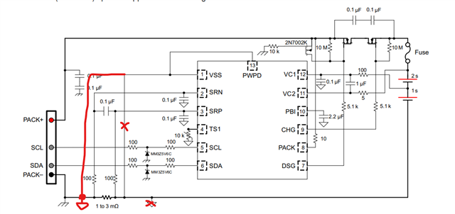
In our BMS the current measurement counts in the balancing current and other consumptions of BQ, because its current flows through the shunt resistor. On the picture you can see the measurement is placed before the BQ so its current can flow through the shunt. Load connects to LGND, but not shown on the schematic.
What kind of problem or consideration would we take if we designed it that way? Sensing the extra current does not effect to the BQ state machine and cause error?
Thank you in advance!