This thread has been locked.

If you have a related question, please click the "Ask a related question" button in the top right corner. The newly created question will be automatically linked to this question.

TPS92643EVM-204: TPS92643EVM-204 discussion

Part Number: TPS92643EVM-204

Hi Team

At present, there are a few questions on the EVB of TPS92643, and I would like to ask for advice.
The environment we use is as follows (details are in the attached file)
1. Input 12V~16V
2. Output 2Pcs LED
3. IADJ adjusts LED output current 0.1~1.7V
4. Connect nExt_PWM to 30Hz, 1ms(low) signal

During the test, adjust the voltage of IADJ. When it is about 0.1V~0.6V, the LED current can increase in sequence and the operation is normal.
But when it is adjusted above 0.7V, the current output action does not keep up with the nExt_PWM signal. I don’t know why?

Excuse me,
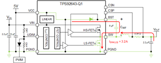
1. To control the switch of the LED output current, is the nExt_PWM pin used?
2. Is there a program to calculate each parameter that you can share?

TPS92643 EVB.pdf

  • The EVM was designed to PWM dim at 100 Hz or higher, based on the bootstrap capacitor selection.  Increase the PWM frequency and you should be ok.  The bootstrap capacitor is getting discharged and then it hits BST UV and the LS fet is turned on the recharge it before starting switching.  The BST capacitor provide the supply for the HS driver, it is a floating driver.  There are limits to how high a value you can go with the bootstrap capacitor, because it can hit negative current limit if you go to really large capacitors.  

    What is the application?  What is the output current range (IADJ is not as informative unless you state the current sense resistor value).  What is the Vf of the diodes at ILED max?  What is the PWM duty cycle range?  

    We don't have a "program" to calculate the values for components, but the datasheet covers the basic calculations.  There aren't that many calculations needed.  

    -fhoude

  • Hi  Fhoude

    Thank you for the support!

    It is mainly applied to the DMS camera to light up the IR LED,
    Using 2 IR LEDs (Vf=3x2=6V@3A),
    IADJ is connected to the Sensor to adjust the current (100mA~2.5A) of the IR LED and adjust the brightness

    nExt_PWM is connected to Sensor to synchronize exposure time and start LED (frame rate=30)
    So the input PWM frequency is fixed at 30Hz, as shown in the attached file

    According to CBST calculation, increase the bootstrap Cap to 6uF, PWM operation can be at 30Hz, but is it recommended to use this way? (below 100Hz)
    Or, is there any other way, you can use 30Hz PWM to control LED On/Off?

  • Hello Kygo,

    At very low PWM frequencies you need to be careful increasing the boot strap capacitor (CBST) between SW and BST.  If the CBST is too large then it can trigger the LS ILIM when you try to charge it.  The reason we generally recommend the larger values of CBST is that you want start switching as soon as UDIM goes high.  If the CBST is charged to above the BST UV threshold then it starts switching immediately.  If it is below the threshold then it turns off the LS FET to charge up CBST from VCC.  It won't turn on the HS fet until the CBST voltage is above the BST UV rising threshold.  That takes time to do, so that means you can get inaccuracies for the average output current based on the PWM  to average output current calculations.  Here is the current path to charging CBST.

    The instantaneous current can be high when using large CBST, thus it can hit LS ILIM.  The way around this is to use a much smaller CBST (on the order of 33nF) for lower PWM frequencies.  It will not start switching immediately, but the delay in charging up the CBST is much smaller and become insignificant when compared to the period of a low PWM frequency.  

    -fhoude