This thread has been locked.

If you have a related question, please click the "Ask a related question" button in the top right corner. The newly created question will be automatically linked to this question.

TPS7H1101A-SP: Stability mismatch between Transient and WCA models

Part Number: TPS7H1101A-SP
Other Parts Discussed in Thread: TINA-TI

Hi,

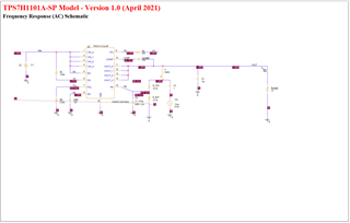
I have a TINA-TI simulation using the TPS7H1101 Transient model, and I'm getting unacceptable ringing in the transient response unless I deviate from TI's COMP capacitor value of 10nF. Wanting to understand that better, I then simulated the same configuration with the WCA model to check the open-loop Bode plot, and was surprised to find I got great phase margin with the 10nF capacitor! Can you help me understand this mismatch in behavior? Is it a mistake in my setup or a difference in the models? Screenshots below.

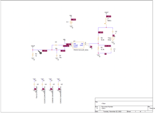
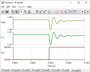
Transient Model Ringing (with 50->100 mA step load):

With the 10nF CCOMP. Ringing implies phase margin <<30 degrees.

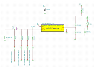
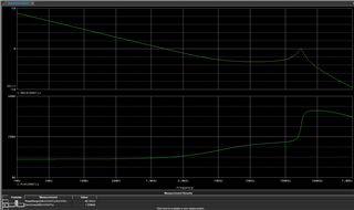
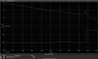
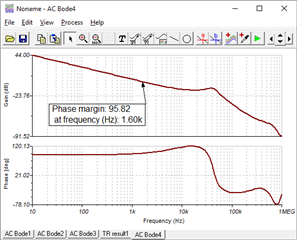
WCA Model Bode Plot (with RL of 100 mA):

Also with the 10 nF CCOMP. Very high phase margin! Hope this one is correct Slight smile Although the crossover frequency looks very low to me.
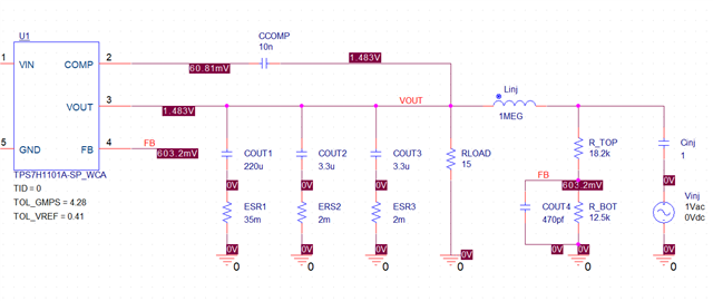
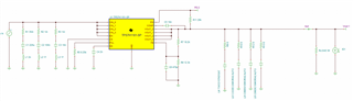
Transient Sim:

(Note the output capacitors are vendor models representative of what we're planning on using)
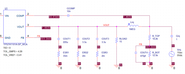
Bode Plot Sim:

VG1 is a cosine with 1V amplitude/0 phase.

  • Azad,

    I am going to take a closer look at this, and check with another team member that may have some insight into the TINA model history.   I am uncertain if this model was tuned for AC analysis.  

    The WCA models were tuned for AC response, and should be more accurate in this respect.

     I should be able to get some additional information soon and reply back. 

    Regards,

    Wade

  • Azad,

    I wanted to give you an update.   I was attempting to validate the models, but I have some issues with my computer.   I think a background software install is making it unusable for simulation.   This should get resolved shortly and I can post an update on Monday.   I apologize for delay.

    Regards,

    Wade

  • No problem! I appreciate it. Have a good weekend.

    Azad

  • Azad,

    The theory that I am going to try to validate when I get my sim capability back is verifying similar circuit in Pspice or Pspice for TI.    The models were developed in Pspice, and sometimes when they get imported into another simulator the simulation quality is not as robust.

    A coworker ran a sim case for me using the WCA model in pspice.  Using a very similar setup (not exact output caps), the same transient with a bode plot shows a crossover of ~72kHz, and PM of 45 degrees.   This is much more realistic.   The Tina PM crossover of 1.6kHz is not real, and should not be trusted.

    If possible, can you use Pspice or Pspice for TI?  The latter is free.  It can be downloaded here: https://www.ti.com/tool/PSPICE-FOR-TI

    Regards,

    Wade

  • Ahhh that's an interesting theory. I can try that next week. I'll let you know what I find.

    Azad

  • Wade,

    I set up an identical simulation in PSpice for TI, including the same vendor cap models and WCA model, and got the same phase margin and crossover as I did in TINA-TI. I then replaced the vendor caps with a simple 10 uF cap, and still got a very similar crossover and phase margin. Could you send me your sim case? I have a feeling I'm missing something fundamental.

    PSpice schematic:

    AC Sweep result:

    Phase margin and crossover frequency calculated at bottom to be 98 degrees & 1.6kHz

    Azad

  • Additionally, I tried to create the exact same circuit with the normal PSpice model. I get similar results--94.2 degrees at 1.8 kHz. I must be doing something wrong!

  • Azad,

    I should be able to get my simulation running today.   I will also confirm the simulation results from my coworker.

    I will update you soon.

    Regards,

    Wade

  • Azad,

    I see the difference that is causing the change in results for crossover. 

    The difference is where Ccomp is connected in the schematic.   Either on the isolated side of the Linj, or device side.

    Our schematics connect to the top of the feedback divider.    My sim results are not exactly as your schematic, but representative.

    with crossover of 67kHz

    vs

    with a Fc of 1.6kHz.

    I would like to confer with some of my counterparts on validity of each.   Since the comp capacitance will not see the injected signal when on Vout node, it makes sense that Ccomp needs to connect to the node with injected signal.   Additionally, the models were validated/created with the schematic included with the project and model.  So, I believe the correct results will be Ccomp connected between inductor and Feedback node.

    Let me know if this improves your results.

    I will follow up with any additional insight.

    Regards,

    Wade

  • Ahhhh, that makes perfect sense. I agree with your reasoning. I believe that also addresses the inconsistency I thought I was seeing between the transient and AC sims. When I connect the CCOMP as you noted, the phase margin goes down significantly and matches what I saw in the initial transient sim. Thank you so much!

    Azad

  • You are welcome.  Have a great Thanksgiving.