A related question is a question created from another question. When the related question is created, it will be automatically linked to the original question.
If you have a related question, please click the "Ask a related question" button in the top right corner. The newly created question will be automatically linked to this question.
UCC28C40: UCC28C40 OUTPUT Abnormal waveform AT FULL LOAD (12V6A)
Reducing R7 decreased the loop gain and the abnormal waveform disappeared. So it is a control loop issue. As Vin or the load changes the instability might return. I recommend they measure the bode plot with a network analyzer to determine the gain margin and phase margin across all expected input voltages and loads.
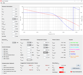
It's easiest and most accurate to measure the loop response. If they do not have a network analyzer in the lab the customer can model their system and compensation using TI's Power Stage Designer Tool. See first picture below.
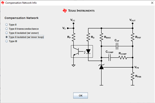
Choose FLYBACK > LOOP CALCULATOR. For the compensation network, use TYPE II ISOLATED (W/ INNER LOOP) but set Rbias to a large value (like 1 Mohm). See second picture below.