Other Parts Discussed in Thread: BQ25792
Hi,
I need to use 'I2Cw' command to write registers to BQ25792 from TPS25750. The recent doc I can't find is 2642.How do I use the Host Interface. But I have some doubts about the 'I2Cw' flow chart.

Q1. Compared with sluvc05a.pdf. Apparently, it misses slave address (bits 6:0) shown in Table 3-15.
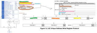
Q2. Compared with Figure 1-2. the 'BYTE CNT' field in the chart should be the 'Byte Count' value in Figure 1-2. But the value 0x08 is bigger than the following data bytes count, but if we take into the *missed* slave device address, it makes some sense.
Q3. I don't know why it shows so many "Register Offset" in an example. It troubles me a lot. Compared with Table 3-15, I guess the Data[3] should correspond to the bytes 3 wihich is labeled "Reserved". And Data[4] is the actual register offset in the slave device. But the remained "payload" data is only 4 bytes. This is conflict with the Data[2] field., which is 0x05.
I see several similar questions on the forum, the most recent one is about 5 months ago. But no one gives clear solution.
Any help?
Thanks.