Hi Team,
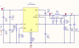
The figure below is the schematic design of LM5164 in customer application. The parameters basically refer to the demo board of this IC, but in the actual test process, the fluctuation range of the no-load output voltage waveform is too large.
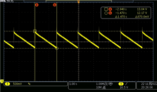
It seems that after the FB pin voltage drops to 1.2V, the PWM start-up time is too long, and the output voltage rises more, resulting in a larger peak-to-peak value of the ripple, reaching 870mV.
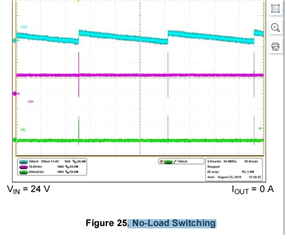
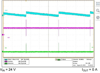
Compared with datasheet Figure25 . No-Load Switching waveform, the voltage ripple is much larger.
If the load is 1A, the switching node waveform is very stable, but the no-load ripple is large, and I want to confirm with you what causes it.
Customers have tried the following:
1. Increase the input capacitance to 4.4uF, no significant change.
2. Change the R253 to 100k, or change the C80 to 1nf, there is no change.
3. Change C109 to 3.3nF, the output peak-to-peak value can be greatly reduced, but this value seems to deviate from our theoretical calculation value, and the load of 1A is not very stable.
So, please also help to see if there is any way to improve the peak-to-peak ripple at no load.
The output voltage waveform is as follows, each time the PWM starts, the output voltage will increase by about 870mV. At this time, the no-load input is 55V, and the output is 12V.