This thread has been locked.

If you have a related question, please click the "Ask a related question" button in the top right corner. The newly created question will be automatically linked to this question.

TPS7A30-49EVM-567: Load regulation become out of range the datasheet specification

Guru 19595 points
Part Number: TPS7A30-49EVM-567
Other Parts Discussed in Thread: TPS7A49

We tested the load regulation for TPS7A30-49EVM-567 on default setting, these spec was out of range the datasheet specification below.

Please let me know about three points below;

・The reason of differ from datasheet specification.

・Detailed test condition for load regulation by datasheet.

・Is there any idea for improve load regulation?

Test results are attached below, 
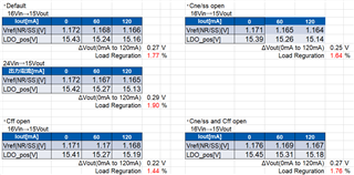
Measured Vnr/ss look like low voltage, but it is no problem because of below E2E thread. 

https://e2e.ti.com/support/power-management-group/power-management/f/power-management-forum/550498/tps7a49-vfb-versus-vref/2072857

By the way, load regulation are not depend on Vin voltage.

Best regards, 

Satoshi

  • Hi Satoshi-San, 

    For the no load condition Vref looks ok. 

    Also, how is the % being calculated? Where is the Vout being measured at, is it right across Cout, or further down the line? 

    I see that there are 3 measurement points 0, 60, and 120 mA, how are these loads being applied?

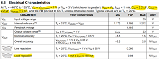
    I will see if I can get a more detailed test condition, however, the Load Regulation spec conditions are Vin=1V+Vout(nom) Ven=Vin, Cin=Cout=2.2uF where typical values are for Ta=25C.

    One way to test this Load regulation is performing a Load Transient and calculating from there. 

    Best, 

    Edgar Acosta

  • Hi Edgar

    Thank you for reply,

    I answer about test condition below.

    ・Calculate method is below;

     (Vout_0A - Vout_120mA) / Vout_average_0A~120mA

    ・Measured Vout point is down the line of Cout.

     But when measured Vout pin, it was the same results.

    ・The way to set load is used Electric load on constant current mode.

    ・EVM default is Cin: 1μF and Cout: 10μF, are these difference possibility to affect load regulation?

    If you have any notice, please let me know.

    Best regards,

    Satoshi

  • Hi Satoshi, 

    Thank you for the clarification, I was doing (Vout_0A-Vout_120mA)/Vout(nominal).

    How long are you waiting to take the measurement? We tend to make the measurement quite fast to prevent any increase of Tj. If you let the device running some time, this can start heating up, and then you get to the overall accuracy of the device which we can see its -2.5% to 2.5% range. 

    Is it possible to retake the measurement using a resistive load instead of the electronic load? 

    I will also try to test this on the bench and compare results. 

    I looked at the Data Sheet for TPS7A49, and it states that the minimum capacitance for both input and output should be 2.2uF, therefore, is it possible to change the input capacitor to a higher capacitance? 

    Lastly, for these measurements we highly recommend using high precision multimeters or at least a 6 1/2 bench top multimeter.  

    Best, 

    Edgar Acosta

  • Hi Satoshi, 

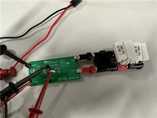
    I went ahead and configured the EVM with Cin=Cout=10uF and installed R3 with 162kOhm||196kOhms and R4 with a 7.5kOhms. All three resistors have a 0.1% tolerance rating. With this configuration we should obtain Vout=15.1885V. 

    I used resistive loads: 

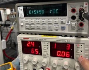
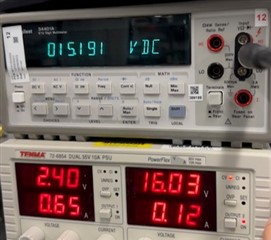
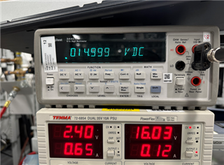
    As you can see for a 60mA load Vout was 15.19V and for a 120mA load the reading was 15.191. Now if we only use these two values, then 

    (15.191-15.19)/(15.1885) =0.0066%

    I measured Vout without any load and it settled to 15.20V.

    If we include this measurement then (15.2-15.191)/15.1885 = 0.0592% which is higher than the typical of 0.04%, yet closer than the 1.7%. 

    Even by averaging the values I still get the 0.0592%

    Let me know if this helps and if you could improve the setup on your end. 

    Best, 

    Edgar Acosta

  • Hi Edgar,

    Thank you very much for reply and test,

    I update test results and other are below;

    ・I guess that temperature is not large affect for Vout, because dropout voltage is small (1V) and increased Tj is about 10℃.

    ・0A load become increased Vout. 

     I retake the measurement on 18mA, 60mA, 120mA. (I want to measure 1mA for the same as datasheet condition, but 18mA is limit of electric load setting)

     Load regulation is 1.46%.

    ・I retake the measurement using a resistive load instead of the electronic load, Load regulation was the same as constant current mode.

    Please consider about additional question below;

    ①About your measured results, are there test data (picture) from multimeter on no load, and output current?

     (Above pictures are only 60mA and 120mA)

    ②Please let me know about detailed test condition for delivered load regulation: 0.04%.

     Or, is there Max spec for load regulation? (0.04% is typ spec)

    ③As a results, TPS7A49 can not deliver the load regulation: 0.04%, correct?

    Best regards,

    Satoshi

  • Hi Satoshi, 

    The test conditions are shown in DS: 

    This is what our Test Engineers follow to deliver the specs seen in our EC table. They use different equipment needed for production. 

    The pictures I showed are for 60mA and 120mA load conditions and it is showing the power supply at 16V for Vin and a bench DMM showing Vout. I can go ahead and retake the measurement for no load and include 1mA and take a picture as well. 

    I would have to dig deeper and see if there is any other information in regards load regulation.

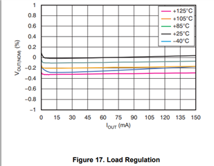
    TPS7A49 is capable of delivering the 0.04% spec, even when looking at the Load regulation plot: 0.04% is doable at 25C. It does shift with temperature, but it is still within a +-1% range (even tighter), and from my bench results I was capable of measuring (15.2-15.191)/15.1885 = 0.0592%

    Best, 

    Edgar Acosta

  • Hi Satoshi-San. 

    I retested the EVM board. 

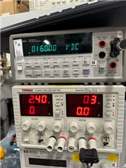
    Here I am just measuring Vin to be 16V

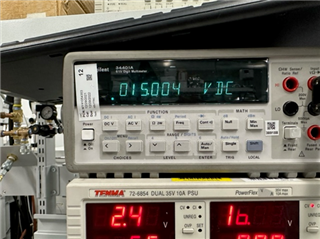
    Here is showing Vout without any load 

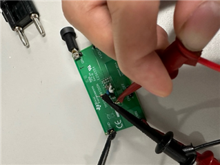
    Then here is the 1mA circuit and measurement: 

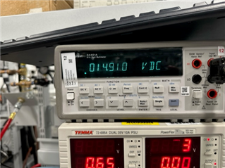
    and I retook the 120mA measurement: 

    With all this, if we follow the DS where 1mA is the minimum load, then we get, (15.004-14.999) / (15.1885) * 100=0.0329%

    or if we use nominal of 15 -> 0.0333% 

    Notice that I am measuring right at Cout. 

    Best, 

    Edgar Acosta