This thread has been locked.

If you have a related question, please click the "Ask a related question" button in the top right corner. The newly created question will be automatically linked to this question.

LM5023: LM5023 Operation Problem

Part Number: LM5023

Hello,

I am working on flyback converter using LM5023

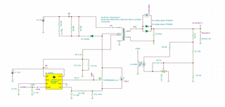
The circuit I have assembled on dot PCB to test with DC source as follows:

Decided rating of the converter is
Input: 85VAC - 230VAC
Output: 19VDC, 3.43A, 65W

The transformer is custom designed and is rated for
PRI : 85V to 300V
SEC : 19V @ 3.5A
AUX : 10V to 12V @ 50mA
Fs : operating 60-to-100kHz (max 130kHz)

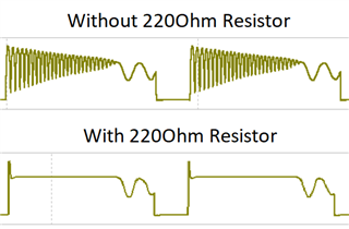
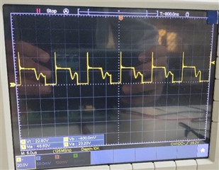
The MOSFET Vds waveform is coming out like this:

1) Why is the peak coming out to be so large even after connecting the snubber circuit to the transformer? 

(Even after using the same snubber circuit as LM5023EVM the this high spike is observed, whereas EVM just gives 64V of spike on practical testing)

2) Also the circuit stops working after 30W of load testing?

  • Hello Raj,

    Exactly what does "...circuit I have assembled on dot PCB to test" mean.  Is this a PCB with soldered components or a protoboard with point-to-point wiring?  Point-to-point wiring has a lot of stray inductance which gives rise to voltage spikes and is not recommended for switching supply testing.

    To answer your questions:

    1) The EVM does not use a 220 ohm resistor in series with the 470 pF clamp capacitor.  If you are using the 220 ohm resistor remove it.  Also, a measurement like this needs to be done with a tip-and-barrel on the 'scope probe.  Using the typical ground wire on the 'scope probe will pick up switching noise and give false readings.

    2) Exactly what do you mean by "stops working"?  Is it still switching (small pulses) or trying to switch in bursts?  Without 'scope pictures, my guesses would be the transformer could be saturating or the CS pin is picking up noise and terminating the gate pulses.

    The EVM used a transformer from Wurth: 750313417.  How does your transformer compare to this one?  What other changes have you made from the EVM design?

    Regards,

    Eric

  • Thanks for the suggestions Eric,.

    I have some more queries regarding it.

    1) When I am simulating the same circuit in TI's Tina software then there was significant amount of high frequency ringing present just after the switch turns off. Then after attaching that 220 Ohm resistor that high frequency ringing was damping out. But yes I will try without it too.

    Also, I had used the same probe for checking the Vds across mosfet in evaluation board also, the peak voltage observed is comparatively very low around 64V. Since the probe is same, is it a probe problem or problem due to using dot PCB?

    2) The meaning of stop working is: the voltage across load falls to zero

    3) I doubt if transformer is getting saturated because the transformer rating are matching with the calculations.
    The major difference between the transformer in EVM and ours is the primary inductance which depends on the minimum switching frequency. 
    For EVM's Transformer it is 70kHz and for our transformer it is 100kHz.

    The voltage rating in input while testing is also on low side(only 135V). Did the shutdown after 30W load may have some different causes?


  • Hi Raj,

    Please tell me exactly what does "dot PCB" mean.  Maybe send a picture.

    The EVM did not use the 220 ohm resistor so I would remove it.  The parasitics in a simulation are very different from an actual PCB, so tuning the snubber in simulation is not advised.

    Can you use an oscilloscope to determine why the regulator stops working after 30W?

    Eric