


Other Parts Discussed in Thread: TMS320F28335
Hi Team,
Question 1
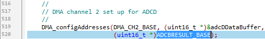
As shown in the figure above, the source address of DMA channel 2 in the routine is ADCBRESULT_BASE. This might be incorrect as the ADC module of ADCD is used. Could you please check it for me?
Question 2
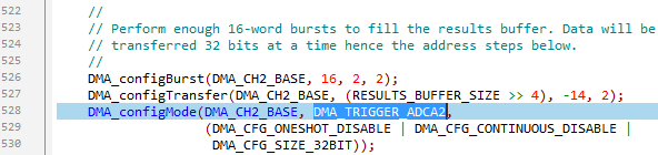
As shown in the figure above, ADCA and ADCD are sampled synchronously, so ADCA2 (ADCA unit's interruption 2) and ADCD2 (ADCD unit's interruption 2) occur at the same time, but in principle, using DMA_TRIGGER_ADCD2 as the trigger signal of DMA channel 2 is more reasonable, isn't it?
Question 3
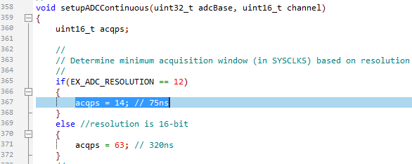
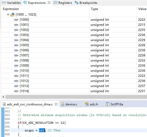
The default sampling window of the project is 75nS. I don't know why in the routine the sampling window is set as such, but for the LaunchPad development board of TMS320F28379D, this sampling time is too short. The sampling results of the input signal of 1.632V are as follows.
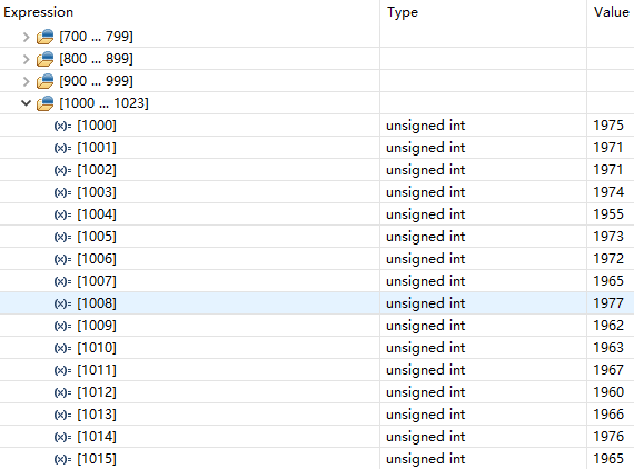
In theory, with an input voltage of 1.632V, a value of 2228 should be generated. But the value in the figure is obviously too small.
After increasing the sampling window, accurate results can be obtained, as shown in the figure below. ACQPS is set as 163.
My calculation is based on the relevant chapter 11.15.2 Choosing an Acquisition Window Duration in TRM, as shown in the figure below.
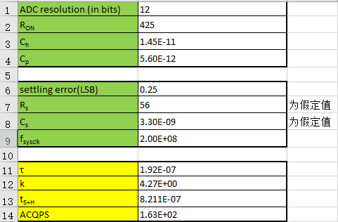
Since each ADC channel of the LaunchPad does not have Rs and Cs, I assumed a set of values, so it may not be accurate. However, I would like to remind everyone to calculate the minimum sampling window when using the ADC unit and be aware that the Cp value of each channel is different.
The CH value of the ADC channel of TMS320F28379D is 14.5pF, while the CH value of the ADC channel of TMS320F28335 is 1.64pF. Although the Ron resistance of TMS320F28379 is 425Ω, which is smaller than the Ron resistance of TMS320F28335, namely 1KΩ. But as the CH value of TMS320F28379D is relatively large, it is recommended to use Relatively smaller Rs resistor to reduce the minimum sampling window to reduce the impact on time-sensitive applications.
Question 4
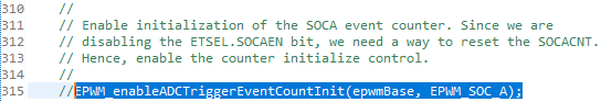
I don't understand the function of the highlighted statement in the code snippet above well. After commenting out, the code runs well without any abnormality
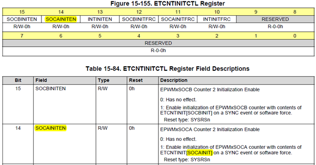
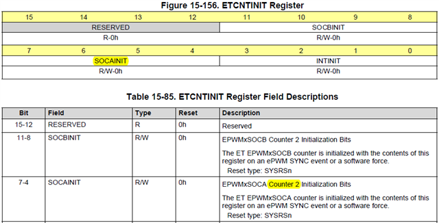
It seems that the initialization of counter 2 is enabled.
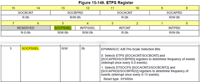
But the routine does not use counter2. I did not find where the SOCPSSEL is configured as 1.
Question 5
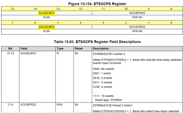
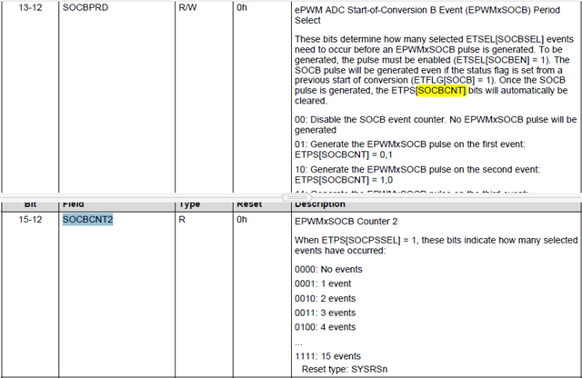
Will SOCBCNT2 (SOCACNT2) be cleared when SOCB (SOCA) is generated? If it will not be cleared, is it necessary to manually clear it?
Question 6
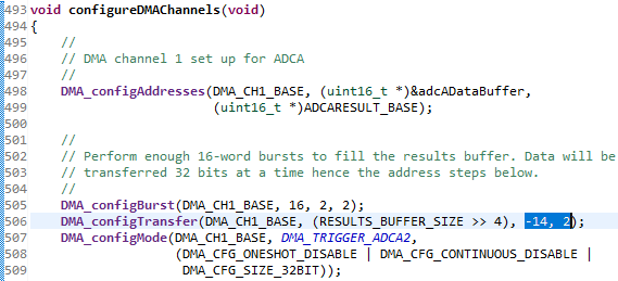
The srcStep is -14 because 16 result registers are transmitted in 32bit size. The address pointer of the last transmission points to ADCRESULT14. Thus, when starting a new burst transmission, the address pointer needs to be subtracted by 14 to make the pointer point to ADCRESULT0. Is my understanding correct?
The destStep is 2. My understanding of this is: because it is transmitted in 32bit size, the address pointer points to addr1.14 in the last transmission, and 16 16-bit results are transmitted each time, so it is necessary to make addr1.14+2 = addr2.0 to start a new storage of 16 16-bit results. Is this understanding correct?
Kind regards,
Katherine

