This thread has been locked.

If you have a related question, please click the "Ask a related question" button in the top right corner. The newly created question will be automatically linked to this question.

LM5164: Frequency Change

Part Number: LM5164


Hi,

I am using the LM5164 IC for buck converter.

Power supply parameters:

Input voltage: 30-60V from batteries

Output voltage: 3.3V, 0.5W

Switching frequency set: 75kHZ

Main inductor is 100uH 

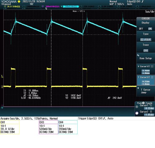
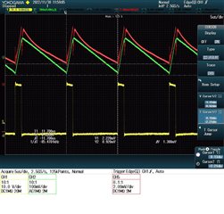
Although i set the switching frequency to 75kHz, the switching frequency changes from 77kHz to 93kHz depends on the input voltage (input voltage rises -> freq rises).

Do you know why?

is this normal operation? there is no issue with my circuit?

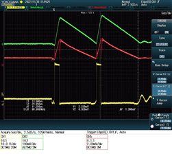
30V input, fsw=87kHz:

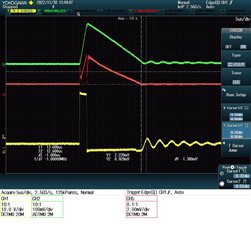
60V input, Fsw=93kHz:
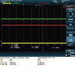
Circuit:


Thank you


  • Hello Maor,

    I reviewed your circuit design and the ripple injection seems more than sufficient.

    With you being in a light load condition, I presume the switching frequency may change slightly with power conditions as this device employs a sleep mode.

    With increased load, ie: 500mA, do you see the same behavior? I would assume in that case the frequency should be nearly constant.

  • Hi Marshell,

    I was wrong, when i change the input voltage the frequency is constant (but not 75k like i set it to), but when i change the load the frequency changes. Bigger load -> smaller frequency.

    Please take a look at the pictures:

    30V input, 10mW load:

    30V input, 500mW load:

    As you can see in the pictures of the 500mW, i don't think i get into sleep mode since i always have pulses and the FB voltage has constant slope (in sleep mode the FB voltage slope decreases)

    When i change the load to 1W or 1.5W, i get frequency of about 84kHz.

    Why i don't get the 75kHz? Is this an issue or its a normal operation?

    Thank you

  • Hello ,

    I do not think you are seeing anything irregular.

    I believe what you are seeing is that the equation for frequency calculation is not a perfect curve-fit.

    In that case, if you want to achieve right on the dot, 75kHz operation, I would advise increasing the RON resistance up to the next standard value ie: 118kOhm,

  • Hi Marshall,

    What do you mean by that the equition is not curve fit?

    Thank you

  • Hello Maor,

    The RON resistance equation is formed by a curve fit, and it may not necessarily be perfect.

    A 5kHz or so off seems reasonable, from similar devices I have evaluated.

    It maybe worthwhile to see if you can see the part to part variance on your application board.

    I am assuming you are using 1% tolerance resistances?

  • Hi Marshell,

    I am using 5% resistor tolerance since this is what i have in the resistors book, if i will use 0.1% tolerance how it will influence the frequency?

    What do you mean by part to part variance? To replace the IC and see the difference?

    Thank you

  • Hello Maor,

    The frequency accuracy will improve with tighter tolerance resistance.

    By part to part variance, I was curious to know if the behavior changes any with a different IC.

    I expect it will not and it is associated with resistance tolerance and imperfect equation in provided in the datasheet.

  • Hi Marshell,

    And do you know why i get higher frequency at lower loads?

    Is it normal operation?

    Thank you

  • Hello Maor,

    Frequency should decrease with lighter loads.

    For the 1st 10mWout scope capture, the SW waveform doesn't appear to go discontinuous.

    For the quoted load current, that would not make sense to me as half the inductor ripple current would exceed the DC load current, so, in that case, the inductor current would go discontinuous which your waveform is not showing.

    With that said, I am unsure if I can make that same conclusion on your measurements.

  • Hi Marshall,

    In my buck i have transformer with 2 more outputs, i disconnected the secondary diodes (left only with the primary winding), and in 10mW output power i get 1 and sometimes 2 pulses in 75kHz between them (like the formula) and than the IC goes to sleep for 1ms (When i connect the secondary's the frequency changes to 88kHz because the off time decreases because the secondary's take energy in off time and this influences the primary current).

    My questions are:

    1. Do you know why i get sometimes 2 pulses instead of always 1 pulse when the secondary's not connected (see the pictures below)? is it normal operation?

    Green - FB pin voltage (AC coupled)

    Red - primary current

    Yellow - SW pin voltage

    2. When i am working with 1W instead of 10mW (secondary's disconnected), the buck is working in CCM mode (see the current in the picture below) and the frequency raises to 85kHz (instead of 75kHz in 10mW), is it because the error in the formula?

    3. Why when i am increasing the load current i get bigger output voltage? 3.29V and 3.4V

    Is it normal operation?

    Thank you

  • 1. Do you know why i get sometimes 2 pulses instead of always 1 pulse when the secondary's not connected (see the pictures below)? is it normal operation?

    In light-load mode, the device's on-time pulse is contingent on VFB dropping below 1.2V. If you may not necessarily see constant frequency operation, especially if your load is dynamic. In terms of stability and proper design of the device, you should be seeing constant PWM operation at full-load and constant frequency. If you are seeing any double pulsing, similar to figure 4, in a full load condition condition, then we would want to further investigate. 

    Source: https://www.ti.com/lit/an/snva874/snva874.pdf?ts=1669842258330

    2. When i am working with 1W instead of 10mW (secondary's disconnected), the buck is working in CCM mode (see the current in the picture below) and the frequency raises to 85kHz (instead of 75kHz in 10mW), is it because the error in the formula?

    With the minor difference in frequency, I am not particularly concerned. It could be some jitter as well error introduced by the 5% resistor you selected

    3. Why when i am increasing the load current i get bigger output voltage? 3.29V and 3.4V

    Is this the secondary outputs? What is the leakage inductance on the XFM?

  • Hi Marshall,

    1. I meant that in 10mW i see 1 pulse and after 75kHz i see another and than the IC goes to sleep mode for 1ms. I dont see pulse and immediately after another pulse like in unstable operation, the design is stable. In 1W operation it is also stable since i see just 1 pulse in 85kHz and constant PWM (In figure 4 i see just 1 pulse).

    My question is: In 10mW load, i dont have to see just 1 pulse before the IC goes to sleep? Why i see 2 pulses in freq of 75kHz before the IC goes to sleep?

    2. What do you mean by jitter?

    3.its the main output. The leakage inductance is ~50nH.

    4. When i am working with 0.5W and in CCM mode, this is what i get in the bode plot:

    I get 50Hz cutoff frequency, is it ok or do i need to get higher cutoff frequency? The PM is 102 and the GM is 62. the PM is a correct result?

    Thank you

  • 1. I meant that in 10mW i see 1 pulse and after 75kHz i see another and than the IC goes to sleep mode for 1ms. I dont see pulse and immediately after another pulse like in unstable operation, the design is stable. In 1W operation it is also stable since i see just 1 pulse in 85kHz and constant PWM (In figure 4 i see just 1 pulse).

    I believe what you are seeing is expected behavior, based on my previous comment and your comment that at 1W/non-sleep-mode, the frequency is constant. This agrees with your component selection being satisfactory.

    2. What do you mean by jitter?

    Slight frequency variation 

    3.its the main output. The leakage inductance is ~50nH.

    The primary/non-isolated output should be tightly regulated over load . For this comparison: 3.29V and 3.4V are you keeping Vin constant? The one think that could impact  output regulation is a wide-spread on injected feedback voltage, which can be caused by sweeping Vin, 

    I get 50Hz cutoff frequency, is it ok or do i need to get higher cutoff frequency? The PM is 102 and the GM is 62. the PM is a correct result?

    Thank you

    That is a low cutoff frequency, though, your inject FB ripple is more than sufficient to ensure stability.

    I would advise following the below equations in the datasheet.

    Your RA, CA, and CB are all very large.

    CB will impact your crossover/transient performance I believe.

  • Hi Marshall,

    About 1, Do i need to see just 1 pulse before going to sleep? couple of pulses and than going to sleep is normal operation?

    Thank you

  • Hi Maor,

    The amount of pulses may not be consistent. The FB voltage is being servo'ed, not the amount of pulses. With that said, in sleep/light load mode, I wouldn't get to hung up on the SW waveform.