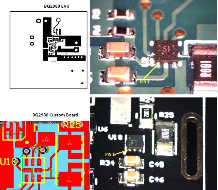
I'm using a BQ298018RUGR in a design and seeing unexpected results. Our circuit follows the EVK design, however when our design is connected to power the protection chip draws ~130mA current, almost all of it through the BAT pin. Also, the BQ2980 doesn't drive the FET switch to pass battery voltage to the system. With the BQ2980 removed from the board current goes to 0.
I am questioning if the board house populated the charger in the correct orientation and/or used the correct part, markings on the chip on our board differ than the one on the eval kit. Below are images of board layout plus images of as build boards for both the EVK and our design with the same orientation (pin 1 should be in bottom left). The marking on the chip is unclear to me, is BQ2980 on the custom board populated in the correct orientation? I notice the "IS" is rotated 90 degrees between the two images, however due to component pin layout it can only be oriented in increments of 180 degrees for placement. Do the markings on our part look correct for a BQ298018RUGR?


