Other Parts Discussed in Thread: UCC256404, UCC24624
Hello TI team.
We are planning to design a dc-dc converter (150Vdc to 24Vdc/15A) using UCC256404 LLC controller and for the learning purpose, we have already bought UCC25640EVM-020 evaluation board. Before proceeding, we have a few basic questions.
- If we understood correctly, the capacitors C1, C17 shown in document SLUUBX3B together make the total resonance capacitance. This placement of caps makes the converter looks like a standard half-bridge converter. What are the pros and cons of not placing them as in a standard Half-bridge LLC converter?
- Do the capacitors C13, C21 and C14 also contribute to resonance?
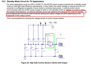
- We are also interested to implement short-circuit protection. How does the controller work in this scenario? Response time? hiccup mode?
- Do you have any recommendations to safely implement short circuit protection?
- We would also like to implement synchronous rectification using UCC24624 controller, any comments regarding the implementation of protection?