This thread has been locked.

If you have a related question, please click the "Ask a related question" button in the top right corner. The newly created question will be automatically linked to this question.

BQ25713: Ripple with super caps

Part Number: BQ25713
Other Parts Discussed in Thread: CSD25402Q3A

Hello TI,

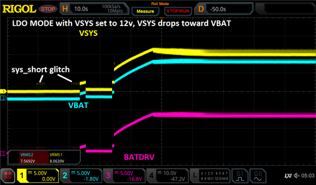
I currently have the BQ25713-evm and I am using it to charge 4 2.7v 30F supercaps to 10.4v.  One, I observe a large ripple when voltage reaches setpoint, and two when I get to my set point I want to switch my vsys to 12v, however this cause my Vbat to fall to 5 volts and slowly recharge back up to 10.4v.  

My register settings are as follows:

{{CHRG_CURRENT, 0x0000},
{CHRG_OPTION_0, 0x0606},
{CHRG_OPTION_2, 0x0275},
{ADC_OPT, 0x80FF}, 
{CHRG_STATUS, 0x0000}, 
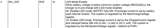
{MIN_SYS_VOLT, 0x0C00},
{MAX_CHRG_VOLT, 0x2740}, 
{CHRG_CURRENT, 0x0A00}, 
{IIN_HOST, 0x4000}, 
{CHRG_OPTION_1, 0x8210}, 
{CHRG_OPTION_0, 0x060E}};

When Vbat gets to my set voltage I change MinSysVoltage to 12v, Ive also tried inhibiting charging first then setting vsys to 12v but in both cases I get vbat knocked down to 5v
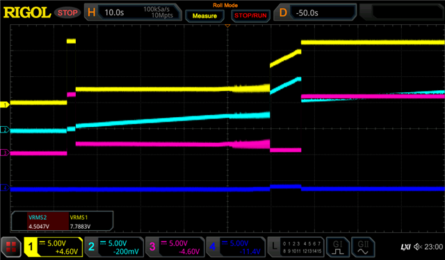
Yellow = Vsys,

light blue = Vbat

pink = batdrv

  • Hello Walter,

    I would like to understand why you are changing VSYSMin during charging? You can set the VSYSMin to 12V and charge the battery even if battery voltage is below 12V (with BATFET in LDO mode). Priority is given to the system regulation.

    Khalid

  • my target VSYSMin is 12 volts but my VBat is 10v.  I set VSYSMin to a low value to enable fast charge mode and then disable charging once I've reached VBat, then I want to change VSYS to 12 volts otherwise it will take around 150-200 seconds to charge the super cap.  

  • Hello Walter,

    I understand. For these devices, we have a recommended procedure for SuperCap charging to bypass the pre-charge mode.

    The BQ25713 has a 384 mA pre-charge current clamp when VBAT < VSYS_MIN, but it is possible to avoid this 384 mA clamp by disabling the BATFET’s LDO mode (ChargeOption0 bit[2] = 0). In this case, the BATFET is fully on, and the BQ25713 will apply the full fast charge current.

    –Note that since the BATFET is fully on, VSYS is not independently regulated above VSYS_MIN.

    Can you try this method?

    Thanks,

    Khalid

  • Hello Khalid,

    Walter has tried this method but unfortunately it did not resolve the issue. To re-iterate the issue, he is controlling the BQ25713 with a VSYS that is higher than VBAT.  It seems to cause a ripple when the VSYS reaches 12v and the VBAT reaches 10V.  

    Do you have any other suggestions?

    Best regards,

    Lucas Pucheta

  • Thank you Lucas, for some additional context as well, I'm running a 2 mOhm rsr for VBAT as described in the app note SLUA913.

  • Hi Walter,

    Can you provide a step by step of what you tried with the method I suggested, i.e. register setting order?

    It seems that when the BATFET is getting turned off (when VSYSMIN is set to 12V) the cap must be discharging into the system. The timescale is very wide on the original plot, can you provide a scope shot zoomed in of the time where the the BATFET is turning off?

    Khalid

  • Hello Khalid, when I implement non-ldo mode as suggested, the charger and battery operate normally, however I'm limited to a system voltage of 10v to match my VBat. 

    My current set up is to configure the registers

    {{CHRG_CURRENT, 0x0000},
    {CHRG_OPTION_0, 0x060D}, 
    {ADC_OPT, 0x80FF},
    {CHRG_STATUS, 0x0000},
    {PROC_HOT_STAT, 0xA800},
    {MIN_SYS_VOLT, 0x2F00},
    {MAX_CHRG_VOLT, 0x2740}, 
    {CHRG_CURRENT, 0x0180},

    {CHRG_OPTION_2, 0x0275}, 
    {CHRG_OPTION_1, 0x8210}, 
    {CHRG_OPTION_0, 0x070E}};

    My current setup is to set registers as above and let it run its course, unfortunately that leaves me with a droop on VSYS when VBat charges up and a ripple on both VBat and VSYS. 


    you can see in this image VSYS is essentially tracking VBat even though its supposed to be in LDO Mode and then gives me a ripple and droops down to vbat. 

    Does operating with a 2mOhm resistor effect the LDO capability to regulate the system voltage and bat voltage?  

    I see on page 56 of the datasheet it says

    "BATFET is fully on when charging or in supplement mode and the voltage difference
    between the system and battery is the VDS of BATFET. System voltage is regulated 160 mV above battery
    voltage when BATFET is off (no charging or no supplement current)."

    Does this mean its not possible to have a higher vsys once the Vbat is fully charged?  

  • Hi Walter,

    I will discuss internally with some of my teammates and get back to you by tomorrow.

    Khalid

  • Hello Walter,

    LDO Mode is only applicable with an adapter present. Otherwise, the system is connected to the battery through the BATFET and these voltages track. Does your application intend to have the adapter always present?

    Regarding the "LDO Mode" bit I sent last week, by default LDO mode is enabled. This means that the BATFET is operating as an LDO when it is below minimum system voltage, and the system can be regulated at a higher voltage than the Battery. This limits the charge current to 384mA, which is why you had to bypass the Minimum System Voltage to quick charge. By disabling LDO mode, the system has to follow the battery voltage during charging, since the BATFET will be fully on.

    After discussion with my colleague, here is what we think the cause of the ripple and drop to 5V is.

    The supercap has a large internal resistance. When the charging is stopped, the supercap voltage will drop due to this resistance. The higher voltage ripple is another indicator of this resistance. When you initially set VSYSMIN<10.4V, and wait till the reflecting point of the CC, CV, then changed VSYSMIN to 12V, this will change the charge current back to PRECHARGE.  The charge current is much reduced then Vcap drops due to internal resistance.

    Just to clarify, if you charge the voltage to above a minimum system voltage (i.e. set minimum system voltage to 10V, charge to 10.4V, disable charge) without ever setting VSYSMIN to 12V, do you see any issues? I understand this is not what your intended application is, I just want to rule out what could be causing the voltage ripple and drop.

    Khalid

  • Hello Khalid, thank you for your response we had to buy a new EVM board as it turns out we were operating outside of the safe operating area of q7.  For reference we are using 4 TPLH-2R7 30F supercaps in series.

    link to datasheet: https://www.tecategroup.com/products/data_sheet.php?i=TPLH-2R7/30WR16X26

    We are prototyping the BQ25713 as a possible replacement for an LTC3350 which using a switching topology to charge the supercaps thereby staying within the SOA.  As we have a hard requirement to get the supercaps charged in under 20 seconds do you have a possible replacement for q7 that can serve this purpose, or an alternative pmic that will fit the requirements?

  • Hi Walter,

    I assume you are trying to charge with >15A to hit the <20s requirement and violating the SOA of Q7. I don't have another FET I can recommend in our catalog. You need a low RDSON FET to minimize conduction loss and I don't see anything in our catalog that meets this requirement better.

    Khalid

  • We are charging with 6 amps, CSD25402Q3A shorted itself across all terminals so I assumed the SOA was violated.  If it would take >15 amps to surpass the SOA, what other reason could there have been to cause the pfet to short like this?  

  • Hi Walter, 

    I was misreading the datasheet, it looks like your conditions are close to the SOA boundary given the VDS is low.