This thread has been locked.

If you have a related question, please click the "Ask a related question" button in the top right corner. The newly created question will be automatically linked to this question.

TPS25750: I2C address setting question

Part Number: TPS25750

Hello expert,

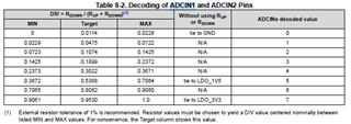
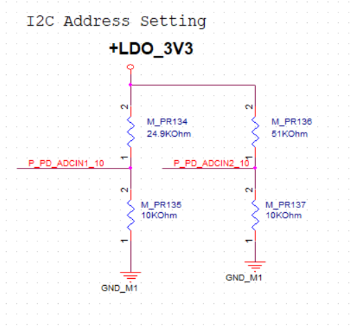
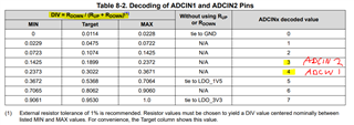
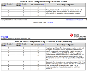
My customer is using TPS25750D and have a question on I2C address setting (by the way you might need to also upload the voltage divider table mapping with decoder value in datasheet). We measured ADCIN1 and ADCIN2 voltage is 0.983V(7) and 0.563(5), based on datasheet we should map to I2C address index #1 which is 0x20. But customer can only find the device at 0x21 but cannot find device at 0x20. May we know if anything else we need to check to know the root cause? Thanks a lot!

Best regards,

Ann Lien

  • Hi Ann,

    Can you double check with customer to see if the ADCINx decode value matches with the table below:

    Thanks and Regards,

    Raymond Lin

  • We've already checked, 7 and 5, I wrote on my post already... Please help to check if there is any other clue...

  • Hi Ann,

    Apologies for the confusion, let me check internally and get back to you by tomorrow. 

    Thanks and Regards,

    Raymond Lin

  • Hi Ann,

    Did the customer use Rup and Rdown for their ADCINx resistor divider or did they use LDO_1V5 and LDO_3V3 to achieve decoded values 7 and 5? 

    I'm testing from end if I get the same results as the customer, I'll update the thread once I get results. 

    Thanks and Regards,
    Raymond Lin

  • Hi Ann,

    After testing from my end, I was able to get address 0x20 with ADCIN1=7 and ADCIN2=5. Let me know how the customer set up their resistor divider so we can continue to debug. 

    Address sweep after setting ADCIN1 to 7 and ADCIN2 to 5: 

    Thanks and Regards,

    Raymond Lin

  • Hi Raymond 

    P_PD_ADCIN1_10 and P_PD_ADCIN2_10 set as follow, ADCIN1 and ADCIN2 voltage is 0.983V(7) and 0.563(5), and 

    we see the address is 22H(7 bit), 44H( 8bit )

  • Hi Ray,

    Based on the provided schematic, I calculated your ADCIN1 and ADCIN2 to decode to 4 and 3 respectively (assuming both Rup and Rdown resistor are populated). 

    ADCIN 1 = 10k / (10k + 24.9k) = 0.2865 -> decodes to 4

    ADCIN 2 = 10k / (10k + 51k) = 0.1639 -> decodes to 3

    This combination is not defined in the I2C address index table, anything outside of these listed combination is not supported by us. 

    In order to achieve the desired configuration, you'll need to adjust the resistor divider feeding into ADCIN1 and ADCIN2. One example s:

    • for ADCIN1, depopulate the bottom 10k resistor  (M_PR135), this will essentially tie ADCIN1 to LDO3V3 which decodes to 7
    • for ADCIN2, replace the top 51k resistor (M_PR136) with 10k which will set the DIV value to be 0.5 (DIV = 10k/(10k+10k)=0.5) which decodes to 5

    Let me know if you have any further questions or concerns regarding the ADCIN setup! 

    Thanks and Regards,
    Raymond Lin