Because of the Thanksgiving holiday in the U.S., TI E2E™ design support forum responses may be delayed from November 25 through December 2. Thank you for your patience.

This thread has been locked.

If you have a related question, please click the "Ask a related question" button in the top right corner. The newly created question will be automatically linked to this question.

LM5022: LM5022 as CV source

Part Number: LM5022
Other Parts Discussed in Thread: LM317HV, LM317, LMP8646, LM5177, LM5118

Hello Team,

                       We have a battery of upper charge limit 54.6. The input is 48V from an adapter. We want to charge it with a max 3A current limit.

We came up with the idea of using the LM5022 as a Constant Voltage source and then use a current limiter circuit. We want to add the LM317HV LDO as a constant current source whose input would be from the LM5022 output. The LM5022 would be turned on with the help of EN pin
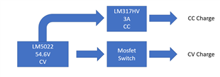
We require help in verifying if this set up would work.

Thanks

  • Hi Bhanu,

    i am noy sure if I understand your block diagram correctly.

    You might check this device as well:

    https://www.ti.com/lit/ds/symlink/lmp8646.pdf

    When using the device, you have suggested you will burn then not required Voltage (=Energy) within the LM317.

    Best regards,

     Stefan

  • Hello Stefan,

                           We want to configure the LM5022 as a constant voltage source with current limit. How do we go about doing it

    Thanks

  • Hello Bhanu,

    Please check out the datasheet of LMP8646, there you can see how you can use a controller with FB node as constant voltage source with current limit.

    Best regards,
    Brigitte

  • Hello Brigitte,


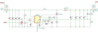
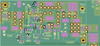
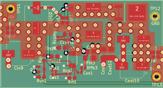
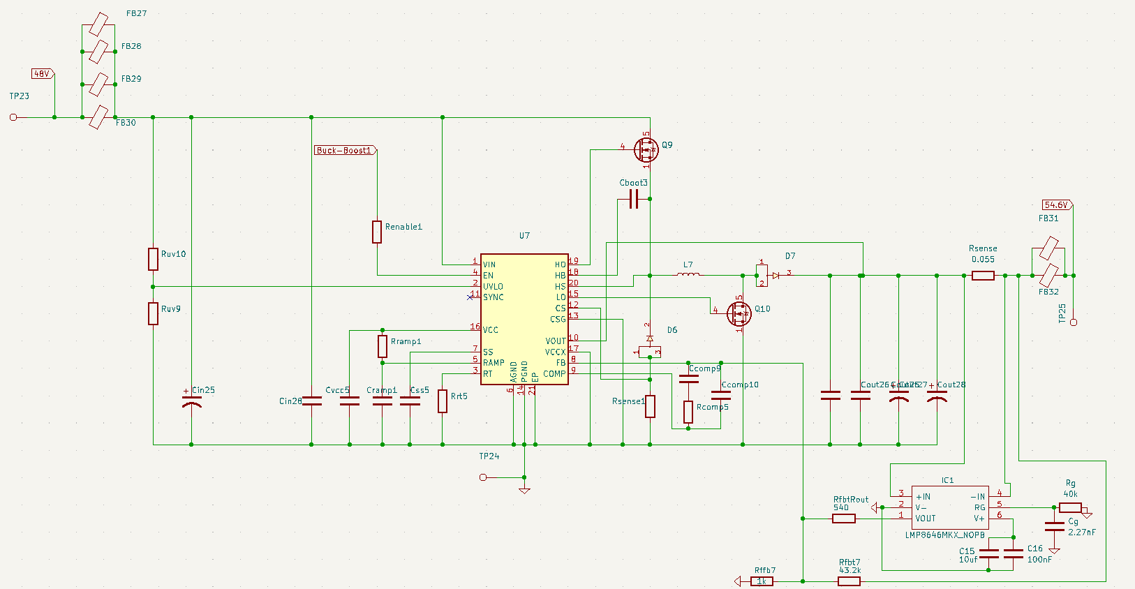
    We have a LM5022MM boost circuit as shown above.The current set during the design on webench was 2A. We used this setup to charge a 54.6V battery. There was no current limiting done by the LM5022. The charge current went upto 4.5A and sometimes even higher.

    I have attached photo of the schematic, placement and PCB layout.

    I would like to trouble shoot this issue as we need to design a new boost circuit for mass production.

    Also is battery charging a resistive or capacitive load as these two are mentioned in LMP8646

    Thanks

  • Hello Bhanu,

    1. Be aware that for input voltages, that are above the output voltage, there is a direct path from VIN to VOUT through the inductor and the diode. So the controller is not able to limit this current. Only for output voltage higher than the input voltage, the current can be limited by the controller.

    2. The LM5022 controller limits the current through the switch, which means that the output current is dependent on the VIN/VOUT ratio. If you want to limit the average output current, additional circuitry like the LMP8646 is necessary.

    I think a battery is considered capacitive load for charging, as the current is at the beginning unlimited like in a capacitor.

    Best regards,
    Brigitte

  • Hello Brigitte,

    How do I configure the LM5022 as a CC source where in the output current is always 3A and the output voltage varies between 38V to 52V. like if I start the battery charging from say 38V the voltage gradually increases to 52 while keeping the current at 3A constant.

    I also notice that the LM5022 is a boost only so how would I go about implementing it for a buck-boost, i.e. buck-boost as a CC source.

    Thanks

  • Hello Brigitte,

    When we connect the battery to the LM5022 configured as 54.6V,2A , The output voltage from the lm5022 drops below 54.6V and current exceeds 4A.

    From what I understood from your explanation is that only if the output voltage is 54.6V and at 54.6V if the current exceeds 2A will the current limit action take place is this right?

    Thanks

  • Hello Bhanu,

    The LM5022 can only limit the output current as long as the output voltage is above the input voltage. If the battery connected to the output has actually a voltage that is lower than the input voltage, the LM5022 cannot limit the current due to the direct path from input to output through the inductor and diode.

    Only if the actual voltage of the battery is above the input voltage of the converter, the converter can limit the current.

    Best regards,
    Brigitte

  • Hello Brigitte,

    One last question

    I will configure the LM5022 for 57V and 4A current. This boosted output will be fed to the input of a charge controller which will take care of the CC and CV transition. 

    I wanted to know if the output from the LM5022 will be constant i.e 57V as long as the the current does not exceed 4A. Input is 48V

    Will the LM5022 act as a CV source even without the LMP8646? as designed according to webench design

    Thanks

  • Hello Bhanu,

    If the output current does not exceed the maximum current limit, the converter will act as a constant voltage source.

    (As long as the external components are selected accordingly.)

    Best regards,
    Brigitte

  • Hello Brigitte,

                        Just a clarification do I need to use the LMP8646 or will the feedback resistors shown in the webench design be enough for a CV source.

    Thanks

  • Hello Bhanu,

    For CV operation, LMP8646 is not necessary.

    This device is only necessary if you want to have CC operation first and then when the load reduces the current need CV operation, like charging a battery.

    Best regards,
    Brigitte

  • Hello Brigitte,

                          So if I use the LMP8646 even if the output voltage is lower than the designed voltage the current limit will be achieved?

    1) So if I design it for 54.6V,3A , then when charging the battery even if the output voltage is only say 42V the output current will be limited to 3A is this correct?

    2) Also we have the LM5022 boost circuit designed for 54.6V and 3A on one PCB board. For testing purposes we want to design the LM8646 on another board and connect it to the LM5022 PCB board. Will this affect the functioning of the LM5022 with the current limit added. What I mean to ask is will the two board connection work for testing purposes or do I need to design both the LM5022 and LMP8646 on the same board for testing purposes

    3) The LM5022 is a boost controller.The input would be 48V and output would be 54.6,3A. When charging the battery from say 40V(Bat Volt) with the LMP8646 as a current limit  the LM5022 output voltage drop below 48V to charge the battery with 3A current. So will this work as a CC source?

    Thanks


  • Hello Bhanu,

    1. Yes.

    2. Yes, if connected correctly and the voltage on the input is below the voltage on the output. If you want to have the current limit functionality at a voltage lower than the input or higher than the input, you need to use a buck-boost converter. E.g. LM5177.

    3. Not if the input is 48V and the output is 40V, as there is a direct path from VIN to VOUT through the inductor and diode that the device cannot control.

    Best regards,
    Brigitte

  • Hello Brigitte,

    So we plan to use the LM5118 as it is a buck-boost.Is this is a suitable part for the CC and CV operation when the Input is either above or below the output voltage as in the case of battery charging.

    Also if we want to use the LM5118 with the LMP8646 with 3A current limit ,what should we enter the Iout in the webench design for the LM5118,like Iout=3A or with a buffer say 3.5A.

    Thanks

  • Hello Bhanu,

    I think with 3A charge current you are at the edge of this device as you need to use 2 diodes. The power dissipation in these diodes might be high. This is the reason why I recommended a 4-switch buck-boost converter like LM5177 (you do not need LMP8646 with this device).

    You should enter the 3A output current and then check with minimum and maximum input and output voltages. For a battery charger, the reaction does not need to be fast normally, so you can use a relatively low compensation.

    Best regards,
    Brigitte

  • Hello Brigitte,

    Just wanted to clarify,if we use the LM5118 configured as 54.6V,3A current limit,then we do not need to use the LMP8646.

    We also noticed that the LM5118 has a current sense pin. So will it always maintain the 3A current limit and drop the output voltage to charge the battery in CC and then move to CV mode?

    Thanks

  • Hello Bhanu,

    With LM5118 you need to use LMP8646 as LM5118 only limits the peak current, not the average current. With LM5177 you could use the internal average current limit loop to work without LMP8646.

    Best regards,
    Brigitte

  • Hello Brigitte,

    Thank you for all the information you have provided me till now,

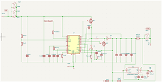
    Could you please kindly just take a look at this schematic of the LM5118 with the LMP8646 connected to it to verify if it is properly connected. I have some doubts as there are COMP pin connections to the FB pin with the help of resistor and capacitor.

    Also in the LMP8646 datasheet they have used 10nF capacitor to connect FB pin to Lout trace. In the schematic I have shard I have not used any capacitor, according to me we have to definitely use a capacitor. Do we go with 10nF capacitor? as there is no formula to calculate the value of this capacitor.

    Or do we not connect FB pin to Lout trace?

    We want to test with the LM5118 as we already have the PCB board for it,so it would be a matter of just changing the resistors and capacitors to 54.6V and achieve 3A CC to charge the battery

    Thanks

  • Hello Brigitte,

    any update on the query?

    Thanks

  • Hello Brigitte,

    We found this in the LM5118 datasheet under current limiting "To further protect the external switches during prolonged overload conditions, an internal counter detects consecutive cycles of current limiting. If the counter detects 256 consecutive current limited PWM cycles, the LM5118 enters a low power dissipation hiccup mode. In the hiccup mode, the output drivers are disabled, the UVLO pin is momentarily pulled low, and the soft-start capacitor is discharged. The regulator is restarted with a normal soft-start sequence once the UVLO pin charges back to 1.23 V. The hiccup mode off-time can be programmed by an external capacitor connected from UVLO pin to ground. This hiccup cycle will repeat until the output overload condition is removed"

    So is this for peak current limiting at 54.6V,3A in our application? or the CC stage of the LM5118 when charging the battery where the voltage would vary between 42V to 54.6V but keeping 3A current limit

    Thanks

  • Hello Bhanu,

    This is for the peak current limit detected on the low side resistor in series to the buck switch.

    Best regards,
    Brigitte

  • Hello Brigitte,

    Could you kindly take a look at the connection of the LMP8646 to LM5118. I have some doubts regarding the feedback and comp connections.

    Thanks

  • Hello Bhanu,

    Please stop asking the same question in several threads and several communication channels. I answered in the other thread.

    Best regards,
    Brigitte

  • Hello Brigitte,

    Sorry for the trouble of asking on several threads.

    We have almost finished our design, we had a question since the battery will be connected to the output of LM5118 always, When the LM5118 is enabled through EN pin during the soft-start time say 2.5ms will the current not be regulated and will it hit the peak.

    Example- Say we are charging from 42V,with the 54.6V output LM5118 with 3A limit set using LMP8646 and peak current limit of 3A in webench design. During the startup if the battery wants to draw 6A will 6A flow through the LM5118 or will it be regulated?

    Since we do not want the LM5118 to get overloaded and short during startup

    Thanks

  • Hello Bhanu,

    LM5118 is a controller, the currenis is not flowing through the device. 

    Best regards, 

    Brigitte 

  • Hello Brigitte,

    Sorry for the misunderstanding, what we wanted to know is the circuit is designed for 3A and the components would be rated for say 4-5A.On startup if there a large inrush current to the battery then the components would not be able to handle it and burn out.So does the LM5118 control the current on startup and should we set the soft start time to the maximum 10ms.

    Thanks

  • Hello Bhanu,

    LM5118 controls the voltage during startup. The current control needs to be done by the external amplifier that controls average current. LM5118 only limits the peak current, but does not control average current.

    Best regards,
    Brigitte

  • Hello Brigitte,

    Yes I understood that, but we are using the LM5118 along with the LMP8646(for average current control).Will the combination of the LM5118 and LMP8646 control the current during startup?

    Thanks

  • Hello Bhanu,

    Yes, with this combination it should work even during startup.

    Best regards,
    Brigitte