This thread has been locked.

If you have a related question, please click the "Ask a related question" button in the top right corner. The newly created question will be automatically linked to this question.

Super Capacitor Charging

Other Parts Discussed in Thread: BQ24640, LM74700-Q1

Hi,

I am looking for product selection support. 

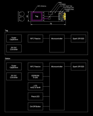
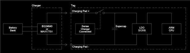
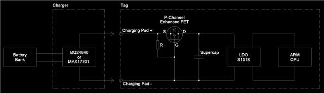
We are prototyping an active UWB tag for a sports timing system. To make the system practical the tags need to be fast charged at the time we register the participants for the event. We propose using a super capacitor as a power source for this reason. We estimate that the total capacitance will be in the vicinity of 20F to power the tag for a maximum of 8 hours. A fast charging circuit is required with a charging time of less than 6s if practical. This would mean approximately 10A at 2.7-3V.

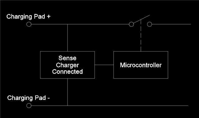
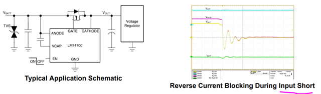
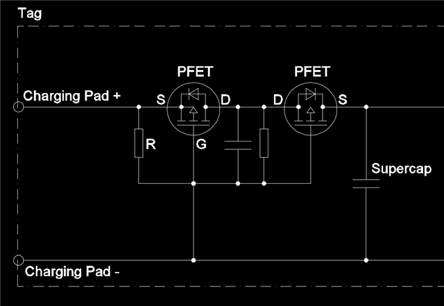
We are looking for a Low QI charger with a 10A 2.7-3V capability with short circuit protection (the tag has exposed charging terminals). The charger could either be on the tag or separate from the tag. For the latter arrangement the short circuit protection would be on the tag.

We have looked at the following;

https://www.ti.com/product/BQ24640

https://www.ti.com/lit/an/slva920/slva920.pdf?ts=1669721110057

Any guidance on a TI product(s) that will help us achieve this would be greatly appreciated.


Kind Regards


Peter Stoneham

  • HI Peter,

    What is your input power source voltage and current for the charger?  A lower voltage is better for highest efficiency.  The power losses make it difficult for a dc/dc converter or battery charger to provide 10A from 0V.  All of our chargers must reduce charge current until the battery (supercap) voltage reaches a voltage threshold.  For example, for BQ24640, when the supercap is less than 2.1 V, the ISET pin is clamped at 600 mV.  That means for a 5 mOhm sense resistor, the current is clamped to 6 A until the voltage reaches 2.1A.

    Regards,
    Jeff

  • Hi Jeff,

    thanks so much for your very helpful response. I didn't realise that the inrush current was limited to 6A until 2.1V when charging supercapacitors. Is this to protect the supercapacitor? Any thoughts on having the charger separate from the tag? The reason for this is that tag power consumption is critical and also the cost/size as there are hundreds of tags in any event. In this case I think short circuit protection is a good idea for the tag to prevent discharging the tag. I have attached a simplified schematic and hardware layout FYI.

  • HI Peter,

    The limitation for any LiIon charger is for the charger current sensing circuit accuracy and also to not trip the charger's short circuit protection since the charger could be starting from VOUT=0V. In theory (meaning we haven't tested) you could lower the sense resistor further to get higher charge current until 2.1V but then you would need to change the sense resistor or, more easily/practically, change the ISET pin resistor to ensure that the charge current doesn't go higher than you want.   

    I agree about short circuit protection.  I see the layout but not the schematic.

    Regards,
    Jeff

  • Hi Jeff,

    Thanks once again for your thoughts on raising the initial charging current - much appreciated! I note there is a BQ24640 evaluation board we can experiment with to see if your assertions are correct.

    I think it makes sense to have the charger separate from the tag. Can I kindly ask if you have any thoughts on a simple short circuit protection circuit/chip we could use on the tag?

  • HI Peter,

    TI makes eFuses and load switches with current limit.  I don't support those devices but have seen other customers use them in schematics with chargers.  The load switches are typically not in the 10A range though.  Not sure about the eFuses.

    Regards,

    Jeff  

  • As you know from one of my links - I had considered an E-fuse for the charging circuit. I am not an electronic engineer so I don't have the technical skills to fully articulate what I am after. In layman's terms I am thinking that a circuit that senses when the charger is plugged into the tag and in turn removed from the tag could be utalised to protect the exposed charging terminals from the possibility of being  short circuited. Does that make sense?

  • Hi Jeff,

    I have drawn up a simple schematic of what could work for our application. Rather than short circuit protection I wonder if we just have a normally open switch (MOSFET?) that is turned on when the charger is connected. Here is a simple diagram of what I am thinking. Does this make sense? Is there a chip that can do this or should I just use discrete components?  

  • Hi Peter,

    The concept is sound.  You can use a PMOS FET with source connected to charging pad + and its ground at ground pad - (assuming the charging pad max voltage < max VGS for FET).  Then the PFET would not come on if there was a short since it needs its Vsource >Vgate+Vths to turn on.  No micro needed for this.

    Regards,

    Jeff

  • Hi Jeff,

    WoW - that was quick! Thanks for confirming that my Layman's concept is sound and for recommending an electronic component. I haven't had time to research what a PMOS FET is yet but maybe you could kindly narrow down my search for a suitable real world TI component? Thanks once again for your help above and beyond what I hoped for!

    P.S. we already have a micro controller so I thought it might be useful...

  • Hi Peter,

    See https://www.ti.com/lit/gpn/csd25501f3

    TI FETs are more optimized for dc/dc converters and you only need a FET as a switch.  

    Regards,

    Jeff

  • Hi Jeff,

    thanks for the suggestion and for your honesty regarding part selection - it is much appreciated! I think I can take it from here. Once again thank you for your time - you have been fantastic sounding board for this non electronics engineer.

  • Hi Jeff,

    sorry to bother you again. An electronics friend said why not just use a diode to prevent accidental discharge. It seems the only issue is the voltage drop and power consumption when charging - even if we use a Schottky diode - as we are using high currents (10A) and using a battery bank as a power source (most of our events are in remote locations). The answer apparently is to use a MOSFET based ideal diode. What do you think of this solution compared to a FET switch and can you recommend a TI ideal diode? I look forward once again to your feedback and recommendation.

  • Hi Jeff,

    I found this document but struggling to find a suitable device; www.ti.com/.../slvae57b.pdf

  • Hi Peter,

    Please use LM74700 ideal diode controller and let us know if you have any questions.

    Best Regards,

    Rakesh

  • Hi Rakesh, thanks for your recommendation - I did look at this as an option - but I don't exactly know how to implement because the power source is a Super capacitor and charging voltages could start at 0V. Here is my interpretation of what I need. Maybe there is a simpler solution??

  • Hi Peter,

    All our ideal diode controller draws power from the ANODE pin and has min working voltage of 3.2V

    Can you mark the position of ideal diode in your block diagram? and why you need to use ideal diode there ?

    Best Regards,

    Rakesh

  • Hi Rakesh,

    Thanks for your response. As mentioned in my initial brief I am looking for a short circuit solution but I am not sure what the best solution is. An ideal diode my not be the solution.

    Once the tag is charged it is disconnected and given to the participant. This is the time that the tag should be protected from short circuit.

    The supercapacitor needs to power the tag for a maximum of 8 hours. Any short circuit protection should not drain power from the tag once disconnected from the charger.

    The maximum charging voltage for the supercapacitor is 3V. The LDO supplies 1.8V to the microcontroller and RF chip.

    My thinking is that the connection between the charging pads and the supercapacitor on the tag be disconnected (open circuit) if it is not being charged. When the charger is connected the connection to the supercapacitor is restored until the charger is removed. A circuit that could achieve this is what I am after and what my diagram shows.

    I hope this explanation helps.

  • Hi Peter,

    Thanks for the detailed description.

    yes, ideal diode is perfect fit to protect from input short conditions at the charging pads. 

    In normal operation, when charger voltage is lower than the minimum operating voltage of LM74700-Q1, the path will be through the body diode of the external MOSFET 

    Best Regards,

    Rakesh

  • Hi Rakesh,

    Thanks for your reassuring response. So what happens when the tag is removed from the charger?

  • Hi Peter,

    When the tag is unplugged, the supply drops and LM74700 disables the exteranl FET to block reverse current flow.

    Best Regards,

    Rakesh

  • Hi Rakesh,

    Disabling a P-Channel Enhancement FET to prevent short circuit is exactly what I am after. I assume that this could be done simply with a resistor (see my updated diagram)?


  • Hi Peter,

    How will it prevent the current flow when your charging pad terminals are shorted ? 

    Or is that fine ?

    Best regards 

    Rakesh 

  • Hi Rakesh,

    Thanks once again for your response. As mentioned I am not an electronics engineer but my thinking is that the FET is turned On by the charger and turns Off when the charger is removed. When the FET is Off no current can flow if a short circuit is placed across the charging terminals. If I am wrong can you kindly explain? Do I absolutely need something like the LM74700 to turn the FET Off?

  • Hi Rakesh,

    I am only trying to draw up what Jeff suggested. Have I got it wrong?

  • I see now that the current would flow through the body diode...

    A friend suggested a Back to Back PFET solution.

  • Ok 

    Let me check on Monday 

  • Hi Rakesh,

    have a nice weekend what is left of it!

  • Hi Peter,

    I have sent you calendar invite. Let us discuss about your requirements on a call.

    Best regards 

    Rakesh 

  • Hi Peter,

    As discussed, please proceed with LM74700 or three terminal approach with discrete PFET solution.

    LM74700 units and EVMs are available for evaluation.

    Best regards 

    Rakesh