This thread has been locked.

If you have a related question, please click the "Ask a related question" button in the top right corner. The newly created question will be automatically linked to this question.

BQ24600: New BQ24600RVAT Design - Rapid MOSFET Heating with no load

Part Number: BQ24600

TIers,

I am hoping for your input on a new BQ24600RVAT battery charger design. The design was mostly based on a TI reference design. The MOSFETs had to be substituted due to availability. The design is intended to be a 24 V input to charge a 12.6 V battery.

When power is first applied to the board even with no battery connected, the supply is pulling max current (7+ A) so it looks like there is a short or miss on the circuit design. When I remove the MOSFETs (2 N-channel single package - HS8K11TB) then the rest of the board operates normally. So it is definitely isolated to the battery charger circuit. This happens even when the CE pin on the BQ24600RVAT is not pulled high.

I have compared my schematic to the reference design and can't find any major differences outside of the MOSFET swap. Connections seems correct on my review. The substitute MOSFET does not support as much current as the reference design, but again, there isn't even a battery connected to charge

There is a chance there is an assembly issue, but 2 out of 2 boards currently have the issue.

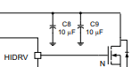
Schematic is attached. The rapid heating is seen in Q4. Thanks!

Kris

BQ24600RVAT.pdf

  • Hi Kris,

    Below is what I found in the schematic:

    It seems like there is no thermistor connected to the TS pin. This can likely put the charger in a non charging state.


    Missing a capacitor at the REGN. It is required to have this capacitor in place.


    Missing capacitor(s) before the source of the hi side FET as these are the required high frequency converter input capacitor(s).

    We recommend having two different ground: analog ground and power ground.

    Regards.

  • Tommy,

    Thank you for the feedback. I will make these changes on the next revision. However, I'm not certain this is the cause of the high current draw through the MOSFET. Would you expect these changes to have an impact even when the Charge Enable is tied to ground?

  • Hi Kris,

    Can I know what is the response of STAT and /PG when this occurred?

    The device should not be pulling this much current (7A) from the supply when there is no battery attached. The charger should only pull the minimum current to do battery detection. There seems to be a short some where but the schematic looks fine. Is WALL_WART connected to any other parts and can you provide the layout file?

    Regards.

  • Tommy, can you provide your TI email address? I cannot post the layout publicly, but I am happy to share the project directly.

    The WALL_WART is powering a few DC/DC converters and a MCU. After removing Q4 from the PCB the power supply output drops to nearly nothing and everything else functions properly so I am confident the issue is in the battery charging circuit. I agree on the assessment of the short, and I agree the schematic seems OK. 

    I will check on the STAT and /PG pins.

  • Hi Kris,

    I will send you a friend request here so we can communicate in direct message.

    Regards.

  • Closing this thread as we move offline.