This thread has been locked.

If you have a related question, please click the "Ask a related question" button in the top right corner. The newly created question will be automatically linked to this question.

LM5146-Q1: Review of LM5146 Schematics

Part Number: LM5146-Q1
Other Parts Discussed in Thread: LM5145-Q1, LM25148-Q1, LM25141-Q1, LM5146

Hi Team,

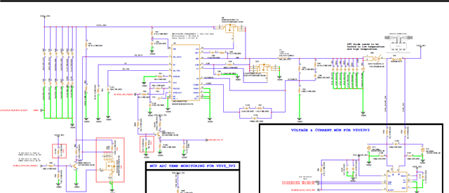
Could you please review the below LM5146-Q1 schematics of our application board. here are the design requirements for our design

Vin minimum = 9V

V typical = 12V

V maximum = 16V

Output current = 10A

Output Voltage = 3.7V

Switching Frequency = 255khz

In addition to above could you also suggest to have EMI Filter circuit for CISPR25 class 5.

Regards,

Chaitanya

  • Hi Chaitanya,

    Given the Vin-max here of 16V, a 100V controller seems overrated. You could easily change to the LM5145-Q1, which is the equivalent pin-to-pin compatible 75V controller. Alternatively, consider one of our automotive 42V controllers, such as the LM25141-Q1 or the LM25148-Q1.

    To review the existing design, please send a completed LM5146-Q1 quickstart calculator file (available by download from the product folder).

    PS: a typical switching frequency for automotive designs is 400 to 440kHz (high enough to reduce passive component size yet below the AM band).

    Regards,

    Tim

  • LM5146-Q1 Quickstart Tool r2 - 48Vin 12Vout 8A 400kHz.xlsm

    Hi Timothy,

    Thank you for your feedback on the alternative solutions. i will look into the same and get back to you.

    Meanwhile please find the Quickstart Calculator file to review the schematics. i have few Questions regarding the same

    1. For compensation loop design - when i simulate the Design inputs the compensation has different values compare to spreadsheet calculator. Which one  should be followed.

    Regards,

    Chaitanya

  • Hi Chaitanya,

    The quickstart tool is accurate but make sure the Cout value is entered correctly (i.e. derated for applied voltage if it's a ceramic). It should generally align with WEBENCH.

    I will review the file you attached and get back to you.

    Regards,

    Tim

  • Two comments on the quickstart:

    Set the current limit at 125-150% of full load.

    50kHz is too high for the loop if Fsw = 255kHz. Typical crossover is 10-15% of Fsw, 20% is the absolute max.

    Regards,

    Tim

  • The schematic looks okay. The series diode on the output will be lossy - is that required? ALso, the compensation values should match the quickstart (make sure to enter the derated value with voltage for ceramic Cout).

    --

    Tim

  • Hi Tim,

    Thanks you very much for the feedback.

    We have added a output diode for following reasons.

    1. We have another 3A , 3.3 V buck converter supplementary supply on the design which we would like to use when application keeps in ultra low power mode by Keeping LM5146 is in shutdown mode to save the power, hence we have diode on the output path for reverse voltage protection. we understand the diode is lossy device.

    2. I follow your inputs by keeping the current limit 125-150% and crossover frequency shall be 1/10 th of switching frequency. we plan to move the switching frequency to 400Khz since other buck converters in the design are working at 400Khz, since it will be easier to design the EMI filter on 12 V input battery. do you have any recommendations for EMI filter, Please provide your inputs

    Regards,

    Chaitanya

  • Hi Chaitanya,

    1. No problem on the diode, although a FET may be more efficient. 

    2. Take a look at the LM5146 EVM (12V/8A/400kHz) for its EMI filter. Given the lower Vin here, you likely won't need a common-mode choke, although it's no harm to include a ferrtie bead for high frequencies. One bead in the positive line provides DM filtering, whereas two beads (one bead each in the positive and negative) provides both DM and CM attenuation.

    --

    Tim