This thread has been locked.

If you have a related question, please click the "Ask a related question" button in the top right corner. The newly created question will be automatically linked to this question.

LM5177: Design Advise for Buck-Boost Converter

Part Number: LM5177

Greetings,

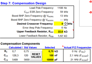
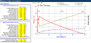
I have designed buck-boost converter with LM5177 using Excel tool (5V- up to 9.4A output, Vin 3-36V, up to 75V Transient)

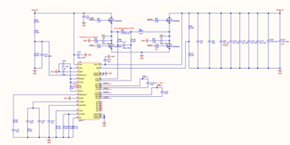
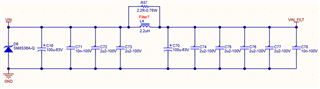
The schematic and EMI filter schematic are attached.

I have a couple of questions as following

1-) In the EVK pin-8 and pin-9 connected to the ground. Shoud I connect them to the ground?

2-) I have added RC Snubber to low side drivers. In the EVK 680p + 3R was used but i have used 680p + 2.2R. Is it okay?

3-) Is there anything wrong in my circuit. Please advise me i can share Excel tool for this design.

4-) For compliance to automotive EMC test, is EMI filter needed? If so please see the attached draft i have used same inductor (2.2u) for filter, is it okay?

5-) For the output capacitors i have used X5R 22uf 10V capacitors since operating temperature range of these capacitors limitted to 85 degrees, is it okay to use them up to 70 degrees ambient temperature?

6-) For the Bootstrap capacitors at SW pins, can caps with a rating of 50V be used if input range is up to 75V?

7-) Should the current sense resistor(R65 2.2mOhm) be pulse withstanding? Is that part number okay(PML100HZPJV2L2)?

8-) In order to prevent reset during cold-cranking, should the output be connected to BIAS pin?

9-) When the LM5177 will be released?

  • Hello Egeman,

    Let me try to answer all your questions:

    1. No, I would leave them floating.

    2. You mean on the MOSFETs, not drivers, but yes, the snubbers are ok. If these are the right ones depends on your MOSFETs and layout anyhow, so they need to be tested on every board.

    3. If you followed the Excel calculator it should be already a good starting point. You might check the power dissipation on your FETs and think about having the ability to parallel a second one if needed. I would not populate them in the first instance, but if there is too much power in one of the transistors, you can add a second one if you have the footprints. Otherwise you need to redesign the board. In addition, I recommend having a resistor on the different digital inputs which are not used now, because then you have the ability to at least check out the other modes without destroying the board,

    4. I assume that an EMI filter is needed on this design, so I would recommend adding one. I think the inductor is ok for a first test.

    5. This depends on how much degrading you allow and how long the system needs to work without failing. The capacitor manufacturer is here the right source, I think. If necessary you could go to X7R with a higher temperature rating.

    6. You can use even smaller caps as these will be always only VCC above their reference voltage.

    7. It seems to be ok.

    8. Makes sense

    9. We expect 1st half of next year.

    Best regards,
    Brigitte

  • Hi again,

    thanks for the replies

    I have additional questions.

    1-) Please see below for compansation values

    in the device datasheet it says "For a robust
    design, the crossover frequency must be less than 1/3 of the RHP zero frequency.". In my design the crossover frequency is as following

    3V - 2.3kHz
    4V - 3kHz
    5V - 3.6kHz
    6V to 7V - 2.8kHz
    8V to 9V - 2.5Khz
    10V to 14V - 2.3kHz
    15V to 36V - 2.1kHz 
    37V to 58V - 1.9kHz 

    >58V, there is a limitation in the excel calculator. Why? I would like to use the same circuit for 48V vehicles as an option. Is it possible?

    2-) What is the allowed range for phase margin?

    3-) For my design the efficiency graph is below.

    why efficiency is mostly lower than 95% ? How can i improve it?

    4-) For EMI filter design, can you suggest on capacitor values?

    Thanks in advance.

  • Hello Egemen,

    What do you have as maximum input voltage in the Excel calculator? If it is 58V, then you get a warning for the voltages above these.

    I think it makes sense to adjust the compensation of the circuit when used in a 24V or 48V system. If you do not want to adjust the compensation, you need to make sure that it works for the whole range and then you need to use the input voltage setting on the calculator for the full range.

    For the EMI filter, please have a look at this thread. The answer there is valid for LM5177 as well: (+) LM34936-Q1: How to calculate the EMI Filter before designing the board or the system - Power management forum - Power management - TI E2E support forums

    Best regards,
    Brigitte