This thread has been locked.

If you have a related question, please click the "Ask a related question" button in the top right corner. The newly created question will be automatically linked to this question.

UCC27611: What is the minimum capactiance on VREF pin

Part Number: UCC27611

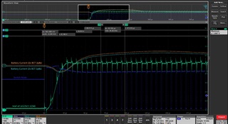
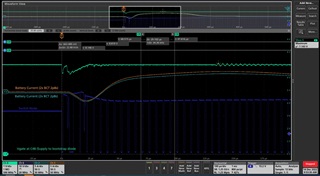
I currently have 0.1uf and 1uF capacitors on the VREF pin.  The issue is that during startup in can take 76usec for the VREF to come up to 5V.  This results in unpredictable switching and no switching during this time.  I would like to know how small a capacitor I can use and still have that LDO remain stable.  

I will say the application is slightly unusual since I am using the UCC27611 as a hi side driver floating on the switch node of a buck converter.  Since is a battery charger so switchnode starts above the input voltage to the UCC27611 so Cref is not charged immediately at startup until the switcher starts switching.

  • Hi Kevin,

    In our application note, Fundamentals of MOSFET and IGBT Gate Driver Circuits, we have an example circuit for how the capacitors could be charged. You would have to change some of the connections to fit your circuit of course.


    To answer your question of what is the minimum capacitance of Cref, that depends on the switching frequency, the gate charge, and the gate to source leakage current of the FET. If you give me those three things, I can get you a rough estimate on what the minimum capacitance is.

    Best Regards,
    Ethan Galloway

  • Interesting.  circuit idea.  There are many things wrong with it since GND of the UC27611 is connected to switch node for a higher voltage (75vin).  I can easily calculate minimum Cref based on gate charge ect. Fsw= 200kHz, Gate Charge = 13nC, Igs is gonna be like 2 mA because I am also powering the isolator off of the VREF supply.  It is the issue of stability of the LDO that bothers me.  Typically the LDO's compensation requires a minimum amount of capacitance to function correctly over temperature etc.

  • Hi Kevin,

    I'll get back to you with more information on Monday.

    Can you send me the schematic that you have currently for the driver?

    Best Regards,
    Ethan Galloway

  • Hi Kevin,

    There are few things you would have to change with the circuit I linked.

    Driver GND would connect to VS.
    DBST is deleted.
    Zener voltage of Dz becomes 5 volts
    CBST becomes CREF.
    The VDD capacitor connects from VCC to VS.

    The main advantage of this circuit is that when Vin is applied, CREF charges. This could reduce your start up time in that case.

    For your circuit as it is, you could also try increasing the capacitance of the VDD cap. This could make the LDO more stable.

    Best Regards,
    Ethan Galloway

  • I see what you are trying to do with that circuit.  If I was planning on respinning the board I might include the startup network.  That is does mean that all the drive current is now coming from 75V which is not the most efficient.  What I really want to know at the moment is how small of CREF I can put on the output of the LDO and still be stable.  

  • Hi Kevin,

    I'm talking with our designers about the LDO stability. I'll get back to you soon.

    In the meantime, what exactly are you seeing the LDO do? Can you send a oscilloscope shot measuring VREF to the switch node? You can use a differential probe to take the measurement or you can use two single sided probes and the math function to take the measurement.

    Also, what's your VDD voltage?

    Best Regards,
    Ethan Galloway

  • The LDO is perfectly stable with 1uF of capacitance, its just that it takes a while to startup (76 usec) because of its current limit.

  • VDD is currently 8V

  • C50a is Cref.  It is floating on the switch node, but you see it slowly ramp up whenever the switch node goes low.

  • Hi Kevin,

    It looks like CREF is having trouble rising up because the switch node is going low only for short periods of time. Will making the switch node stay low help the charge time?

    Which signal is the switch node by the way? Can you take the differential of CREF and the switch node?

    Best Regards,
    Ethan Galloway

  • I reduced the capacitance to 0.1 uF for Cref and things look much happier.  Startup is mor  like 20usec.  I don't have control over the duty cycle its starts at.  That is determined by some undocumented startup delay time in ancient TI regulator I am using.  The duty cycle is sufficient I looked at VDD for the UCC276111 and it snaps up to 8V on first switch cycle.  Its just the current limit of the internal LDO.   I can't take a differential measurement very well because minimum input voltage is 43V and my diff probe is only rated to 42V..  You have to infer the switch node from the voltage on the Cref which floats on the switch node.  And yes the switch node is going all the way to zeroish volts.

  • Does 20 us work for the circuit? What speed are you looking for?

    You can use two single sided probes and use the math function to create a differential measurement.

    If we need to debug more, can you put the SW signal and the UCC27611 VDD signal on the oscilloscope? Keep in mind, the GND reference for this device is SW. If you subtract SW from all the UCC27611 signals, that would make understanding the graphs a lot simpler.

    Best Regards,
    Ethan Galloway

  • got a pretty poor Diff probe.  Here is the voltage on VDD, Vref, and vgate (bootstrap supply voltage).  All measured on seperate waveforms since I only have one probe.  I am still wondering what the smallest stable value I can have on the vref pin.  These waveforms are with 100nF on Vref directly  + 100nF on Vref at some distance from the UC27611

  • Hi Kevin,

    Thanks for your measurements. These graphs are a lot easier to read.

    I'm looking at your measurements. It looks like you may be at the limit of the LDO VREF capacitance. In general for GaN FETs, you should not go above 6 volts. Decreasing the capacitor more may increase the noise which will increase the risk of the FET getting damaged.

    Which signal does Vgate correspond too?

    To further increase the rate at which VREF charges up, increasing the VDD voltage might work. This method works well on the EVM.

    Thanks for being patient with this. I am still looking for a way to calculate the minimum capacitance for VREF and I am still talking to the design team about this.

    Best Regards,
    Ethan Galloway

  • Hi Kevin,

    I have talked to the design team and the lowest value capacitor of VREF we can recommend is 1 uF. Any lower and the performance of the LDO starts decreasing and we can't say whether or not the LDO will work.

    Keep in mind, the VREF capacitor filters noise from the LDO signal and provides power to the gate driver. If the capacitor is too low, the rise/fall time may start increasing.

    Best Regards,
    Ethan Galloway