- Ask a related questionWhat is a related question?A related question is a question created from another question. When the related question is created, it will be automatically linked to the original question.
This thread has been locked.
If you have a related question, please click the "Ask a related question" button in the top right corner. The newly created question will be automatically linked to this question.
Hi Sir,
We want to set the TPS552882-Q1 to PFM at light load, but we can hear the audible noise when our system power on.
When we set the mode to PWM, we did not hear the audible noise while the system was powered on.
I am curious why the PFM will make the audible noise, we can't see the mention from the datasheet.
We set the PFM by tying pin15 to Ground via 24.9kohm as the datasheet mentioned.
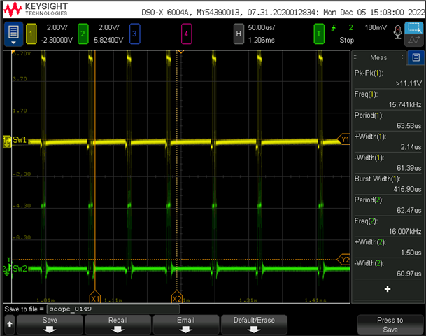
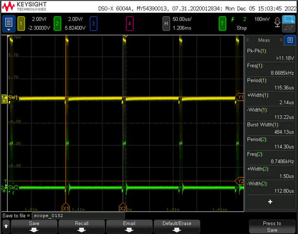
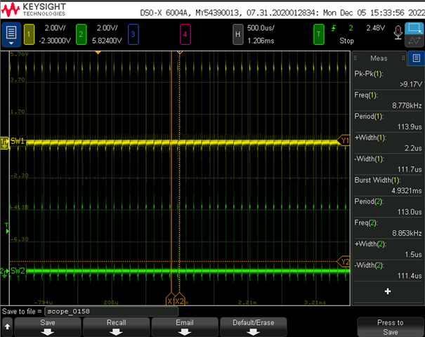
I have attached our schematic TPS552882-Q1, our original mode setting is PWM. I also attached SW1 and SW2 switching waveforms when I heard the audible noise.
Please let us know any design issues to cause the problem, and any design change can prevent the audible noise sound.
I also attached the audible noise sound that I heard.

Hi Godfrey,
Thanks for query on E2E.
PFM is enabled for high efficiency at light load so it will cause discontinuous operation, and from the SW waveforms, we can see like 14kHz and 8kHz audible frequency. You can also see audible frequency ripple from output voltage and inductor current which would cause noise on output capacitors or inductor.
To totally avoid audible noise of PFM, you can change to FPWM mode to obtain constant switching frequency. Or change the material of capacitor or inductor may also help here.
Regards,
Bryce
Hi Bryce,
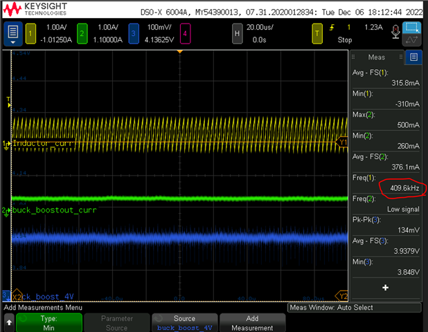
Do you know if we set the mode to PFM? What's the switching mode is when buck-boost output at heavy mode? And I saw the switching frequency still is around 50khz, it did not go to PWM 400khz. Our input voltage to buck-boost is 4.3V and the output voltage from buck-boost is 4V.
If we set PFM mode at light load, could we make it auto-switching to PWM mode when buck-boost enters heavy mode?
PFM heavy mode
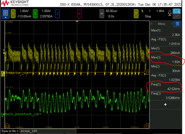
PWM switching frquency
Hi Godfrey,
1. What's the switching mode is when buck-boost output at heavy mode? And I saw the switching frequency still is around 50khz, it did not go to PWM 400khz. Our input voltage to buck-boost is 4.3V and the output voltage from buck-boost is 4V.
-> Even we set PFM mode, at heavy mode, the device will also enter continuous conduction mode. The first waveform above seems like unstable.
2. I see the RFSW=22.1kHz which should set fsw be 890kHz, please change inductor to higher value because too small could cause loop instability. In this case, please at least ensure the inductor value higher than 2.2uH.
3. I also see PG and CC pin connect to I2C, may I ask why you design with this since TPS552882 is non-I2C version.
4. What is the input voltage range? Output is 4V/2A, right?
Regards,
Bryce
Hi Bryce,
1. For the first questions's feedback, what did you mean buck-boost will enter continuous conduction mode. Is it a PWM mode? Is the frequency reach to 400khz on continuous conduction mode?
2. Can the TPS552882 do the auto switch from PFM to PWM or PWM to PFM based on different output loading if we set mode to PFM?
3. The PG and CC pin is reserved to TPS552882 I2C version, due to avoid the components shortage issue, but we will use non-I2C version in our design.
4. The input voltage range is 4.3V to 4.5V, and the output is 4V/2A (the 2A current consumption is the worst case).
thanks
Hi Godfrey,
1. For the first questions's feedback, what did you mean buck-boost will enter continuous conduction mode. Is it a PWM mode? Is the frequency reach to 400khz on continuous conduction mode?
-> Yes, you can also see it as PWM mode, the switching frequency is 400kHz.
2. Can the TPS552882 do the auto switch from PFM to PWM or PWM to PFM based on different output loading if we set mode to PFM?
-> Yes, the difference between PFM and FPWM is only at light load, when at heavy load, they both enter PWM mode.
3. I see the RFSW=22.1kHz which should set fsw be 890kHz, please change inductor to higher value because too small could cause loop instability. In this case, please at least ensure the inductor value higher than 2.2uH. And see it is still unstable at PFM.

Regards,
Bryce
Hi Bryce,
1. If our current design will make the loop instability, what it will happen on the power rail?
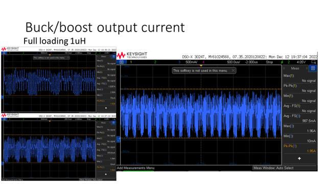
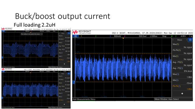
2. I have tried to modify the power inductor from 1uH to 2.2uH and 4.7uH, but it seems like the ripple current and ripple voltage do not have too much impact. Could you help provide more suggestions on this. Please check my test result.
3. If the loop instability, what kind of test we can do to make sure it is stability or instability? ex: phase margin, gain margin and ripple.
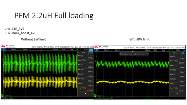
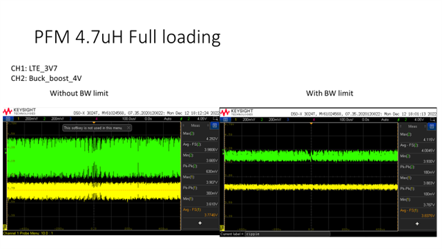
Hi Godfrey,
Thanks for waveforms.
I have some questions about the waveforms,
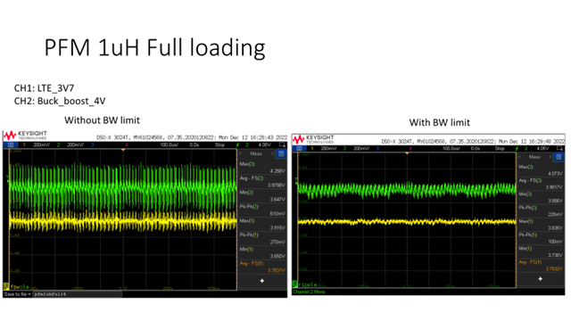
1. What is the LTE_3V7? Is the input voltage of the Buck-Boost?
2. Why the output current is oscillating? Is it caused by the output of Buck-Boost or the loading device? What about replacing with an e-load to do the test?
3. If our current design will make the loop instability, what it will happen on the power rail?
-> When the loop is unstable, the output voltage may have some oscillation and the duty cycle is not fixed. And in worse case, it would cause other issue on the device.
4. I have tried to modify the power inductor from 1uH to 2.2uH and 4.7uH, but it seems like the ripple current and ripple voltage do not have too much impact. Could you help provide more suggestions on this. Please check my test result.
-> I am confused about the output current because I don't see that large ripple on output voltage. Can you forward with the layout of this device? Sometimes poor layout may also cause this problem.
5. If the loop instability, what kind of test we can do to make sure it is stability or instability? ex: phase margin, gain margin and ripple.
-> We can do load transient test to see if the output voltage can recover fast and without too much overshoot/undershoot. Also, you can also test the bode plot of this device.
Regards,
Bryce
Hi Bryce,
1. LTE_3V7 is another buck converter output power rail for LTE module, and the converter input voltage connect to buck-boost ouptut side. Just make sure the ripple voltage won't impact the back-end power rail 3.7V.
2. I think the output current oscillates is from the back-end loading device, I have checked the e-loading won't have oscillates.
3. I think the high ripple voltage is coming from my measurement point, I scope the ripple voltage on the output caps 100uF, when I change the measurement point from C40 caps to after R86 bead, the max ripple voltage is around 200mV on our system full loading.
4. When you said we need to modify our power inductor from 1uH to over 2.2uH based on our current switching frequency setting. Due to the inductor footprint can't allow we change larger power inductor for higher current and higher inductor value. So could we modify our Rfsw (R149) from 22.1kohm to 10kohm, the switching frequency will change from 888kz to 1.92Mhz. That's means our inductor should select over 0.6uH, so we could keep the current power inductor. It seems the audible noise will solve when I set higher switching frequency for the buck-boost converter. Do you think this modification is okay from your perspective any other compensation components need to change?
5. Attachment the load transient waveform based on the different switching frequency for loop stability test, it seems like no too much different, and the ripple voltage a bit higher.
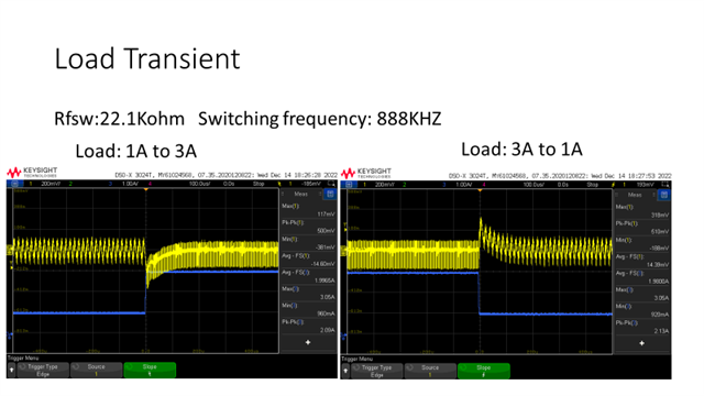
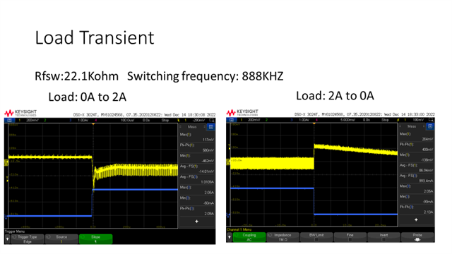
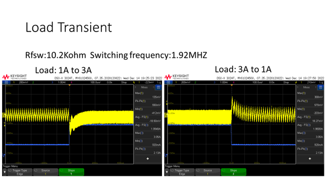
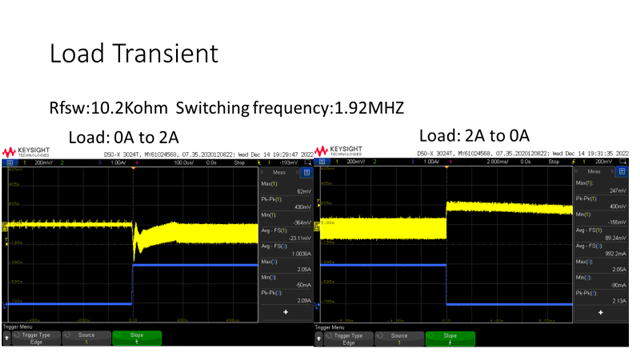
Godfrey
Hi Godfrey,
Thanks for the test waveforms.
1. LTE_3V7 is another buck converter output power rail for LTE module, and the converter input voltage connect to buck-boost ouptut side. Just make sure the ripple voltage won't impact the back-end power rail 3.7V.
2. I think the output current oscillates is from the back-end loading device, I have checked the e-loading won't have oscillates.
-> It's ok with the anomalistic output current only if the output voltage is stable and doesn't affect the post-stage power supply.
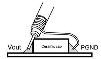
3. I think the high ripple voltage is coming from my measurement point, I scope the ripple voltage on the output caps 100uF, when I change the measurement point from C40 caps to after R86 bead, the max ripple voltage is around 200mV on our system full loading.
-> To test the real ripple voltage of the output voltage, the followed ground ring test method is recommended and we used to test the cap voltage which is closed to output pin.
4. When you said we need to modify our power inductor from 1uH to over 2.2uH based on our current switching frequency setting. Due to the inductor footprint can't allow we change larger power inductor for higher current and higher inductor value. So could we modify our Rfsw (R149) from 22.1kohm to 10kohm, the switching frequency will change from 888kz to 1.92Mhz. That's means our inductor should select over 0.6uH, so we could keep the current power inductor. It seems the audible noise will solve when I set higher switching frequency for the buck-boost converter. Do you think this modification is okay from your perspective any other compensation components need to change?
-> Yes, change to higher frequency is also a method without replacing the inductor. The compensation parameter is ok.
5. Attachment the load transient waveform based on the different switching frequency for loop stability test, it seems like no too much different, and the ripple voltage a bit higher.
-> It's ok with the test results, also we recommend use the ground ring test to measure the real ripple voltage.
6. By the way, we have High Power Density Buck-Boost Converter TPS631000 used in low Vin applications. For more details, please refer to the product page.
Regards,
Bryce