Hi,
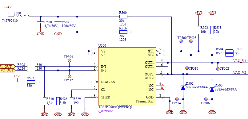
I am observing unexpected power loss in at TPS2H000A chip. It is around 0,5 Watt and the conditions are following:
t(a)=22 deg.C, V(VS)=24,0 Vdc, V(IN1)=V(IN2)=0 V, No load at OUT1, OUT2 (nets VAC_V1, VAC_V2 left open), pull-ups for no load detection=20 kOhm, steady state the consumption from PSU +24V is measured around 23 mA. I was not able find any information about this idle current in TPS2H000A datasheet. Or is it there and hidden to my eyes?
I am sure with the current measurement, it is related to IC and the open load det. bias clearly, because I measured it at location of L500 which was desoldered for this measurement.
My next finding is that when at least one of outputs is slightly loaded e.g. Rload=1 kOhm (while control input still left inactive/off) the output voltage drops below the open load threshold V(ol,off) 1,6 V(min) then the current consumption falls to around 4 mA which is fine because it corresponds with datasheet parameter I(off,diag)=3 mA(max) and open load det. bias +24V->R500(20kOhm)->Rload(1kOhm)->GND.
Otherwise the IC is working fine. But why there flows such "significant" idle quiescent current is a mystery to me.
If anyone can comment this situation, I would appreciate it.
@support.TI: May be if this IC behavior is normal in such conditions, there could be some datasheet information added.
Thanks to everyone in advance.
Note1: Datasheet I have downloaded,
https://www.ti.com/lit/ds/symlink/tps2h000-q1.pdf?ts=1670248674151&ref_url=https%253A%252F%252Fwww.ti.com%252Fproduct%252FTPS2H000-Q1
Note2: My observation is based on eight IC occurrences (I have 2 boards, each assembled with 4 TPS2H000A)
Schematic1: My application of TPS2H000A:

