Because of the holidays, TI E2E™ design support forum responses will be delayed from Dec. 25 through Jan. 2. Thank you for your patience.

This thread has been locked.

If you have a related question, please click the "Ask a related question" button in the top right corner. The newly created question will be automatically linked to this question.

BQ40Z60: Cell Grid

Part Number: BQ40Z60

We have data from our experiments, charge - discharge cycle. On every cycle, we record the R_a value and also the cell grid.
The TRM said that the cell grid value represents the updated R_a value at the present grid point.
We notice that when our cycle stays between RSOC 20% and 80%, we usually are not able to get grid point above 7.
We understand that this is expected because it needs to be discharged deeper to achieve update for higher grid points.
Surprisingly, we also notice that the R_a 8 to 14 has been updated even when the cell grid never reached that high.
My question is, how does the R_a 8 to 14 is calculated even there's no grid point updated?

Attached experiments log files, that experiences updated R_a 8 to 14 value even no grid point updated.

Ra and cell grid.zip

  • Hello Asfan,

    During normal Ra updates we do forward scaling to higher Ra grid points. This is so we can remain accurate even if the application does not fully discharge to 100% DOD. A ratio of the new values calculate at the present grid point is what is used to forward scale the Ra table.

    Sincerely,

    Wyatt Keller

  • Hello Wyatt,

    How does this forward scaling calculated? Is it similar to the fast scaling? For example if the last cell grid updated is grid 7, and it was found that at grid 7 the new R_a is 10% higher, does it mean that the new R_a for grid 8-14 will also be 10% higher than previously? Or is the scale different for each grid? For example in the form of exponential function, where the higher the grid, the higher the scale will be?

    If in the case of continuous shallow DOD and inaccuracies have been accumulated due to long term scaling instead of real update (measured value), will doing 1 cycle of deep discharge enough to do correction if the difference is quite huge? Or is there any limitation on how much correction is allowed?

    Thankyou,
    Asfan Fiirizky

  • Hello Asfan,

    The ratio should be scaled forward in the same as the grid it was calculated at, so if the current grid changed by 10%, the other grids will be scaled by 10%.

    Sincerely,

    Wyatt Keller

  • Hello Wyatt,

    Thankyou so much for your respond, I understand. 

    But If in the case of continuous shallow DOD and inaccuracies have been accumulated due to long term scaling instead of real update (measured value), will doing 1 cycle of deep discharge enough to do correction if the difference is quite huge? Or is there any limitation on how much correction is allowed?

    Thankyou,
    Asfan

  • Hello Asfan,

    You can find the Ra table update disqualification information in the TRM, the gauge does not allow updates if the accumulated error is more than 2%. Also it won't matter if there are many small discharges, if the battery is allowed to relax between them we will correlate the DOD to the OCV and correct for the errors. The gauge requires some relaxation periods for the algorithm to work correctly (update Qmax and reduce charge accumulation error).

    7.4.6 Ra Table Update Conditions

    Sincerely,

    Wyatt Keller

  • In our use case, we often have short charge-discharge cycle but there is very seldom relaxation or any OCV condition. Can you explain more about charge accumulation error? How is it calculated and what are the parameters involved?

  • Hello Asfan,

    You will need to periodically get a relaxation - discharge - relaxation in order for the Qmax to update, this is part of the impedance track algorithm. If you don't periodically do this cycle the accuracy will degrade with time since the Qmax is never updated.

    What is the % amount that you are discharging and charging? Do you have an example load profile?

    Sincerely,

    Wyatt Keller

  • Hello Wyatt,

    Can you please explain more about charge accumulation error first? We understand that Qmax update is important, but our main issue now is that we are seeing a lot of resistance inaccuracies possibly due to the cell grid not updating. From your previous explanation, this might be caused by accumulation error being above the 2% threshold. We tried searching for explanation of accumulation error in TRM but couldn't find any. Can you please explain to us how this accumulation error is calculated and what are the parameters we need to check to verify if this is actually what happened in our case.

    Thankyou,
    Asfan

  • Hello Asfan,

    If this is related to your other thread my response will answer both. Impedance track has a difficult time updating the Ra table during very pulsed or noisy loads since the voltage may not actually reflect the direct IR drop at the present DOD point the gauge is tracking.

    Sincerely,

    Wyatt Keller

  • Hello Wyatt,

    Okay I understood, however we still have an issue where we find that cell grid is seldom updated even in the cycle where the discharge pretty far (under 10% RSOC), is it because there's a R_a update condition doesn't met the requirement? Could you explain more about the charge accumulation error? 

    Thankyou,
    Asfan

  • Hello Asfan,

    The charge accumulation error is not a straight forward calculation, it essentially takes all the possible noise readings that could be passed charge and accumulates over a time period while in relax. If the expected error is over 5% it will disqualify the update. The longer the time in relax the longer the time it may lead to a higher error.

    Sincerely,

    Wyatt Keller

  • Hello Wyatt,

    Okay, I understand, I do appreciate for your fast respond.

    Then, if there's any noise reading from CC during long relaxation period (Could you determine, how long it is? an hour , 5 hours, or more?), that could degrade gauging accuracy with rarely updating the R_a because charge accumulation error above 2%. Therefore, before we're use our battery pack, is there any procedure that we need to accomplish? Is it REST or VCT procedure? Correct me if I'm wrong, by implementing REST and VCT, that will reset the passed charge value to 0.

    Thankyou, 
    Asfan

  • Hello Asfan,

    As I mentioned in the other thread, I don't believe this is related to the accumulation error, I have only rarely seen this feature become an issue. Usually the gauge would have to be in relax for a very long time with no discharge, or the pack capacity is very low (less than 500mAh). I think the bigger issue may be how noisy the load is which makes the Ra table update almost impossible.

    Sincerely,

    Wyatt Keller

  • Hello Wyatt,

    From your previous explanation, it seems like your biggest concern is regarding the pulsed load since this could result in the BMS getting the wrong R_a reading.

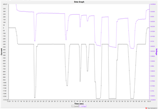
    I tried to run some tests using an oscilloscope (Fluke 199C) where the pack is first given 300mA load and then increased to 1300mA. There seems to be a delay respond (600ms) for the voltage to drop as the result of this load increase. I can see how this could potentially mess with the resistance measurement since the real time voltage doesn’t correspond with the actual load applied. 


    However, when the same test was run using the plotter feature from BMS software with 250ms log interval, I notice there’s no delay in voltage drop following the increase in current. 

    So I guess the question is whether the ADC of BMS current and voltage measurement behaves the same way as oscilloscope or the plotter feature? If it is similar with the plotter figure, where there’s no noticeable delay in voltage drop when there’s load increase, there shouldn’t be any issue with having pulsed load. Am I understanding this correctly?

    Thankyou,
    Asfan.

  • Hello Asfan,

    The gauge ADC is a delta-sigma type, so it is constantly taking samples and essentially averaging over a time period. I think it's strange your measurements show such a long delay with no time constant type exponential for the batteries. Generally even if the voltage drops immediately this is only the R component of the battery model, all of the stages of RC's in parallel will change the behavior of the waveform for the gauge to calculate the cell resistance.

    https://www.researchgate.net/figure/Schematic-Diagram-for-R-RC-RC-RC-Battery-Model_fig35_306240899

    Sincerely,

    Wyatt Keller

  • Hello Wyatt, 

    all of the stages of RC's in parallel will change the behavior of the waveform

    Okay, I understand. It's pretty difficult to measure the battery voltage without any interference from capacitance effect on the procedure of my measurement. From your explanation, it means that the BMS reading behaves like the plotter feature. 

    taking samples and essentially averaging over a time period

    So, do you mean that resistance measurement is based on some sort of moving average value of the measured voltage and current?

    I think the bigger issue may be how noisy the load is which makes the Ra table update almost impossible.

    We've tried to do some tests, to compare the effect of pulsed and constant load, in the same battery pack and environment. 

    Pulsed vs Constant Current.zip

    So, from those data, we did find that what you're suggesting was correct. Once we applied constant load the resulting R_a table was significantly lower than when we were using pulsed load.

    However, we also notice that despite of the lower R_a table, the compres value still remains within the same range. The compres value actually increased continuously and reach a huge value (Above 2500).This ended up causing an issue, where we were experiencing FCC and RSOC drop. The question is, based on your explanation previously compres should be dependent on R_a table and temperature only. Yet, in our case with lower Ra table, we still getting the same compres even though the temperature for both cases are similar. How could this be possible, if there's no other parameter affecting compres value?

    Will there be a situation where the compres value reach below 0?

  • Hello Asfan,

    It's not a moving average, it's just the architecture of the ADC is essentially an average of the current during the conversion period, which is 250ms.

    That's similar to what I would expect since it is correlating a large voltage drop with lower current so it assumes the discharge is in almost constant current (or with low frequency compared to ADC sampling)

    I think what may have occurred is that the gauge switched to the other Ra table that still had high values, CompRes is based on the active table being used, if you do multiple cycles and it is at room temperature CompRes should be similar to the Ra table.

    CompRes should be capped at 0 since it is based on the Ra table which cannot go below 0mOhm.

    For this load it may be better to use a CEDV based gauge so that it is focused more on the coulomb counting rather than voltage correlation.

    Sincerely,

    Wyatt Keller

  • Hello Wyatt,

    the gauge switched to the other Ra table that still had high values

    Can you elaborate more on this? Which other Ra table are you referring? Is it the difference between Ra and Rax?

    Thankyou,
    Asfan

  • Hello Asfan,

    The gauge uses two Ra tables since it is updated often and we want to prevent flash wear out over the lifetime of the pack. I'm checking with the firmware team about exactly which table is used, if we assume there's not much difference between Ra tables during operation then we could use the Ra table from a previous update. Since your Ra table is fluctuating so quickly this could cause the behavior I mentioned where it uses the older Ra table data.

    Sincerely,

    Wyatt Keller