This thread has been locked.

If you have a related question, please click the "Ask a related question" button in the top right corner. The newly created question will be automatically linked to this question.

TPS65023 - DEFDCDC1 Connection

Other Parts Discussed in Thread: TPS65023

Hi There,

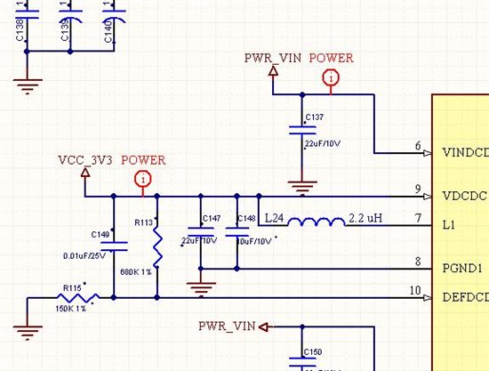
This is regarding the TPS65023 PMIC.  We are using DCDC1 of TPS65023 to give 3.3V output and to do that we have connected resistance as per data sheet suggestion.

DCDC2 is 1.8V and  and DCDC3 is 1.2V. 

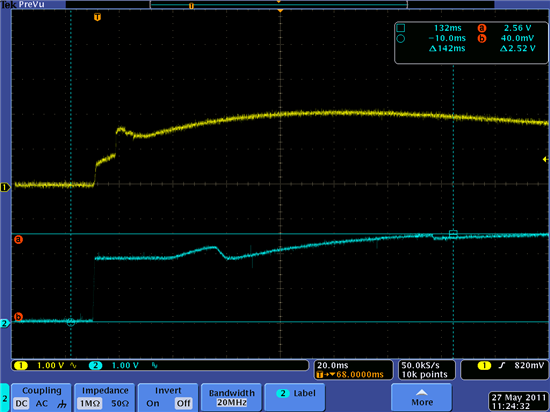
The design works absolutely fine at room temperature. we got proper output voltage and sequence as per design. Sequence is 1..8V => 3.3V =>1.2V. However we found that at 6degreeC temperature design fails. we are unable to get 3.3V properly.

We used freezer spray to cool down U33 area ( power supply PMIC) and we saw that during power up, the 1.8V is ok, 3.3V is not stable (around 2-3V) and 1.2V is not even starting (since 3.3V is not stable).

 We tried to measure the FB line )DEFDCDC1( but it looks like there is no major difference between normal operation and when there is a problem.


As for now, we suspect the following:

·         1. 3.3V buck inductor.

        2. DEFDCDC1 connection. Although it is according to the application note, it is still strange, this pin is not FB line according to the datasheet, but it is referenced to VOUT (3.3V in our casE). We suspect that there might be some kind of race on this line.


       The Schematic can be found on the link attached for power supply section.

                          2451.TPS65023_POWER SUPPLY.pdf


        Thanks

        Rizwan


  • I am using Freezing spray to reduce the temperature - When board is powered up and we use spray to reduce the temperature we found that  - at around 6 - 7 degreeC 3.3V deeps to 1.38 V and it starts varying  1.38 to 2.7V, after some time when temperature rises above 19degC it gets stable at 3.3V.

    Let me know if any further suggestion of direction to debug the issue.

  • Will you please provide an oscilloscope screen shots of the issue?

    Also, does your layout match that of the TPS65023EVM (http://focus.ti.com/docs/toolsw/folders/print/tps65023evm-205.html)?

  • Hi Daniel,


    I checked the behavior in oscilloscope but I didn't save those waveform. I will try to capture behavior today and post the waveform here. However, the behavior is very clear that - when I Freeze the power supply section once board is powered up during rising temperature near to  +6 to +12degC suddenly 3.3V deeps to lower value around 2.70V than It stays at that value than start varying from 2.70-1.30. It stays at any voltage within there for seconds 5-6 seconds and than slowly starts increasing and may be after a minute it reaches to 3.3V again .Behavior is varying board to board in terms of Temperature at which it falls by +/-6 degC and Time take to get 3.3V stable once it has dropped to lover value.


    As long as layout is concern - I am really not doubting that. We have not followed the layout 100% as EVM but it is quite good and we had get it reviewed by local TI FAE.

    I am doubting the defdcdc1 pin connection - Y'day I tried lower value of voltage devider  on that pin [84.5K and 18.2K instead of 453K and 100K] - It helped me to resolve this issue in one board but unfortunately on different board same issue occurred [ofcourse with laser frequency earlier board was failing 5 out of 5 time I do the experiment but now it fails 3 out of 5 times].

    Please suggest if any direction.

  • Does the condition occur if you short the ferrite bead?


  • Increasing the current through the feedback resistor improves your immunity to noise. Layout is still the number one suspect.

  • I too had the same issue with my DM365 based design. We were also using the same configuration like

    DC/DC1 for 3.3V

    DC/DC2 for 1.8V

    DC/DC3 for 1.35V.

    We also had same condition, what we found is the issue with the power sequencing. our sequencing was 1.35V->1.8V->3.3V, 3.3V was our last power supply.

    Main culprit was a capacitor(c149) that we added in the feed back loop of 3.3V


    Due to this capacitor the  3.3V is getting ramped before the 1.8V get stabilized. causing the internal clamp diode of DM365 to latch and cause the 3.3V supply to come on 1.8V power rail


    Wave form is shown below:

    yellow is 3.3V ramp and blue is 1.8v