This thread has been locked.

If you have a related question, please click the "Ask a related question" button in the top right corner. The newly created question will be automatically linked to this question.

BQ76200: Switching Problems

Part Number: BQ76200
Other Parts Discussed in Thread: BQ76940, BQ78350-R1

Dear E2E Team!

In our actual design we're using the BQ78350-R1, its companion IC BQ76940 and the BQ76200 for highside switching.

But we are facing issues in some of the devices, where the BQ7200 won't turn on the FETs reliably, instead it goes into some sort of hiccup mode as described in chapter 2.1 in SLUA794.

We already doublechecked all component values and design recommendations according to SLUA794, SLVA729A and the datasheet itself. The values should be correct in terms of our design.

Now we're not sure if there is anything wrong in our design that we don't see. 

As VDDCP capacitor we're using a 4u7 X7R for overall 12 MOSFETs (6x CHG, 6xDSG) for a 14S application. The input capacitance of one MOSFET is Ciss = 5600pF.

We're not sure if we should change the capacitor value or if it is better to take higher gate resistors. I want to share our schematic design also, for reference:

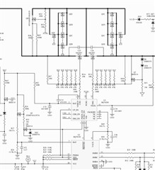
Figure 1: Actual design layout

Also here you can see how the BQ76200 in our design behaves.

As mentioned, there are just few devices whit this issue and we also couldn't recognise any error patterns or when this problem occurs:

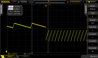
Figure 2: BQ76200 Hiccup Mode

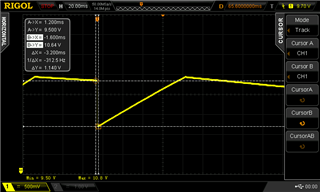
Figure 3: Successful switch-on on the same device as in Figure 2

Also I want to share the measurement of the gate current measured over R46 (100R on CHG side) and over R43 (100R on DSG side)

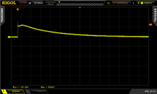
Figure 4: Gate current on CHG side measured over a 100R resistor

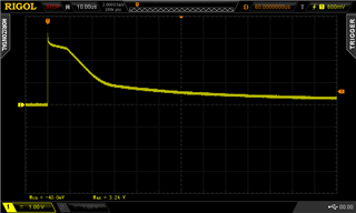
Figure 5: Gate current on DSG side measured over a 100R resistor

By the way, we can reproduce this failure only if we load the battery with a resistive load. In our case its approx. 3R @ 53V battery voltage

Thank you in advance for your help!

  • Hello Battrick,

    That is interesting. You could attempt increasing the FET pin resistors and see if there's any differences in the switching. Possibly a few hundred Ohms to few kOhms. Something I notice is that your Q1A/Q2A MOSFETs have a 10-Ohm gate resistances, while the rest of the FETs have 47-Ohm, you may want to have all of these the same so there's minimal difference in their switching.

    Something else to note, is that we also recommend to add a Zener and resistor in series between the PACK and DSG pins to minimize losses during the switching. This is also mentioned in SLUA794 in Figure 12. Would it be possible to add these and see how switching is affected?

    Best Regards,

    Luis Hernandez Salomon

  • The problem has been found:

    The boost capacitor C33 was 10uF, 25V. Which sounds reasonable. But for some reason this capacitor did not do its job. We installed a new capacitor and the circuit worked flawlessly. 

    We had no access to the datasheet of the capacitor used. Meaning we could not figure out why this particular capacitor was not suitable. 

  • Hello Lukas,

    Glad to hear the problem was fixed!

    Did you replace it with a different 10-uF, 25-V capacitor? It would be interesting to know what differences these capacitors had.

    Best Regards,

    Luis Hernandez Salomon

  • Hello Luis,

    the C33 was replaced by a 10µF 50V X7R. We chose a 50V type to get a better capacity reserve due to the voltage derating.

    There are still ongoing tests, but the new capacitor shows a much better performance. We did not have any switching failures till now.

  • Hello Battrick,

    Thank you for letting me know! That's interesting, typically 25-V should be enough for the voltage rating. Best of luck in your design!

    If there is any other questions, we will always be here to answer Slight smile.

    Best Regards,

    Luis Hernandez Salomon