This thread has been locked.

If you have a related question, please click the "Ask a related question" button in the top right corner. The newly created question will be automatically linked to this question.

UCC28600: Coilcraft "GA3544-BL" Pspice model

Part Number: UCC28600
Other Parts Discussed in Thread: TINA-TI, TL431, TLV431

Dear members,

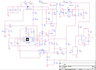
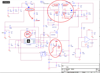
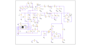
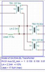
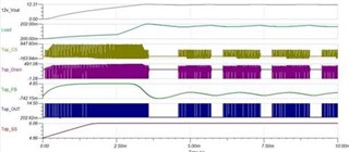
I try to make a simulation of PWR050 of TI designs which use the "GA3544-BL ". I know that there is problem in using this transformer and coupling factor. I don't know how to solve it. You can see the sch of the circuit that I want to simulate below:

4454.PWR050A_SCH.pdf

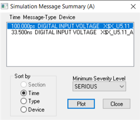
I will attach the simulation too. Any suggestion would be highly appreciated. 


3441.UCC28600D.zip

Thanks

Farzaneh

  • Hello Farzaneh, 

    Thank you for your interest in the UCC28600 flyback controller. 

    I can open .PDF of the 4454.PWR050A schematic file, however, I am unable to open the STAR.DSN file.  I do not have that software.
    Can you please resend your simulation schematic as a PDF?  
    Here is a copy of the GA3544-BL transformer datasheet, in case you don't have access to one: GA3544-BL.pdf

    I would not expect that there would be a problem in modeling this transformer. 
    Can you please explain what the problem is you are having with the transformer and its coupling factor?  

    Regards,
    Ulrich

  • Dear Ulrich,

    this is the SCH with the last update. Now I have problem with UCC28600.

    4034.PAGE1.pdf

    I could export a DXF file in orcad and then I convert it to pdf. it's a bit messy and I dont know why it doesn't show everything correctly. I sen you a screen shot of it too.

    I wish you can find the problem there.

    Also, I think there is an error with iniciating in chip. this is the fault that shows me ORCAD

    Thanks

    Farzaneh

  • Hello Farzeneh, 

    Thank you for the schematic screen shot.  Yes, the ORCAD pdf is too messy to view easily.  Fortunately the screen shot has high resolution and is very clear.

    I have made a copy of it and added mark-ups: 

    1. The GA3544-BL has a 2.3mH primary inductance and has turns-ratios of 1 : 0.0158 : 0.158 : 0.079.  Working backwards and iterating, I find the actual turns can be 38 : 6 : 6 : 3.  The winding inductances reflect from the primary value by the turns-ratio squared, so I marked up the reflected inductances as they should be.

    2.  Remove C20 from across R25.  This cap will distort the current sense signal. 

    3.  Change R4 to 620ohms and connected across pins 1-2 of U4 (as indicated).

    4.  Change diode D6 to MBRS1100T3.  1N1200 is not a suitable part for this application. 

    In your schematic, the winding L4 has a polarity such that it reflects the primary voltage during the MOSFET on-time.  In other words, it is acting as a forward-mode winding, not as a flyback winding.  Is that your intention?  
    Also, M1 is modeled with 2N6762 which is a 500-V rated FET, and it is a very old part.  I suggest to find a modern MOSFET with 600-V rating. 
    But if it is for simulation purposes only, maybe it will work okay. 

    Unfortunately, I cannot debug the ORCAD error message shown.  I don't know anything about ORCAD.  
    Maybe if you make the changes that I suggest, the system will run properly.  
    If it is a timing issue, maybe you need to set a shorter minimum time step for the simulation.  

    Regards,
    Ulrich

  • Dear Ulrich, 

    I made the changes you mentioned previously but it didn't work. I made part by part the simulation and I think that the pspice model is not working because I tried to simplify the simulation in order to make the UCC28600 model work but I couldn't. Can you tell me how I can make sure the model is working?

    I run out of time and I need to get some results of this component. I highly appreciate your time and effort

    Thanks

    Farzaneh 

  • Hello Farzaneh, 

    I have acquired the PSpice for TI software and can open a .DSN file now.

    Please provide a zip-file of your latest set of model files and I'll see if I can get it to run.  I make no promises, but I'll try to see if I can get it working.  

    Regards,
    Ulrich

  • oh that's fantastic. I'm gonna send the last update. I could make the transformer works converting 400v to 12v with the ratio that u can find in the sch. But still the chip doesn't work. 

    inductors.rar

    Please le me know if u can open the files 

    Farzaneh

  • Hi Farzaneh, 

    I can't open a .rar file.  You sent a .zip file before. Please send your latest simulation files in a zip-file.  
    Also, the name of the .rar file is "inductors".  May I presume that there is more than inductor data in the archive?
    I suggest to give the zip-file a more appropriate name.

    Thanks and regards,
    Ulrich

  • Hello Farzaneh, 

    I am sorry that I am unable to get the UCC28600 PSpice model to work. 
    I received a similar error message as you did concerning some DIGITAL INPUT VOLTLAGE X$X... at 1.2ns.  
    I don't know what it means and I don't know how to fix it.  No one else around here does either, since none of us are PSpice experts. 

    Aside from that, there were a number of circuit errors in your schematic diagram, including missing the changes that I indicated in my mark-up above. 
    I made those changes and I also had to remove all of the diode and FET models and replace them with generic models from PSpice. 
    I had to replace the optocoupler with a generic current-controlled current source.
    Here is a zip-file of my circuit for reference: UCC28600_CKT2.zip

    Here is an image of it:

    My only suggestion at this point is to try using the TINA-TI model instead of the PSpice, to see if that one will work: https://www.ti.com/lit/tsc/slum608

    Modify the TINA-TI file to match the circuit image here. 
    I hope that simulation will work for you.  

    Regards,
    Ulrich

  • Dear Ulrich,

    I really appreciate your effort. Unfortunately I don't know how to work with TINA. I tried couple of times but it was so time consuming for me. I will try again because I do need to run this simulation.

    Thanks a lot

    Farzaneh  

  • Dear Ulrich,

    Happy new year. I wish you have had nice vacations. I tried to simulate the circuit using TINA. There are some errors that I can't solve as I'm not very familiar to TINA.  May I ask you to take a look at it?

    I don't know how to model the optocoupler. The other thing is the transformer. i'm not sure if I made it correctly. I used the transformer datasheet.

    chrome-extension://efaidnbmnnnibpcajpcglclefindmkaj/www.mouser.es/.../ga3544-463400.pdf

    I will really appreciate it 

    Farzaneh

    1351.PWR050_UCC28600.zip

  • Hello Farzaneh,

    I found a number of issues in your model that I corrected in this file UCC28600 - 20230105.TSC, but I still can only get a single pulse out of the UCC28600 controller. 
    I don't know what the problem is and need more time to figure it out. 

    However, I thought it best to give you a copy of what I have to see what the changes are: 
    1. Transformer model constructed from ideal transformers and external inductors.  I'd stay away from the non-ideal model unless you really understand it. (I don't.)
    2. Changed MOSFET model to 600V device, adjusted its parameters.
    3. Changed several diodes for higher voltage, non-schottky. 
    4.  Added a diode to the opto-coupler model and revised bias resistor across them.
    5.  Disconnected to major circuit portions and grounded their inputs to minimize impact on simulating the main power stage. (They can be reconnected later when the basic power works.)
    6. Changed TLV431 to TL431.  TLV431 has low reference voltage.

    An opto-coupler is modeled as a current-controlled current-source with a ~1.2V diode at the input and high value capacitance across collector-emitter pins.  
    This model is already in your circuit. 

    I'm sorry that I can't get it to work better.  For some reason the controller stops switching after a single pulse, but I don't know why (yet).
    I'll try to work on it some more.

    Regards,
    Ulrich

  • Dear Ulrich,

    I don't know how to appreciate all your effort. I could understand everything you've explained for modeling in TINA. There is sth that I couldn't understand. When we take a look at the transformer datasheet we can see that the "converting relation" (I don't remember the exact name in English, so sorry) is inverse. 

    I mean what I highlighted in the photo. I wanna know how you model it in TINA.

    Thanks a lot

    Farzaneh

  • Hello Farzaneh, 

    I believe that "converting relation" translates into "polarity".  The polarity of the various windings with respect to each other is indicated with polarity marks.
    We often call them polarity dots, too. 

    Using the above diagram, if a positive voltage is applied across the primary winding (Pri) (+ on pin-1 (the dot), - on pin-2), then a positive voltage will appear at the dotted terminals of all other windings with respect to their non-dotted ends.  This also works if a negative voltage is applied to the dot... all other windings will have negative voltages at their dots. 

    Actually, it does not matter which winding is forced (which has the voltage actively applied), the polarity of all other windings follows the polarity markings. 
    In a flyback transformer, for example, if winding S1 has +Vout at pin-8 during the demagnetization phase of a switching cycle, then pin-2 will have a positive reflected voltage of Nps*Vout with respect to pin-1. 

    In the TINA model that I sent to you, I did not know how to use a non-linear model so I used the Ideal Transformer model.  Also, I do not know how to add more windings to the model, so I just added several Ideal Transformers with their primary windings connected in parallel.  Since the Ideal model has infinite primary inductance and zero leakage inductance, I added those parameters as lumped elements.  Lm (at 2.3mH) is across the ideal primaries and Llk (at 17.6uH) is in series with one of the primary leads. The specific turns ratio for each secondary winding is entered at N2, where N1 = 1 in all cases. 

    Even though some of the polarities are not shown as "inverse", you can connect the external circuit to get the same effective inverse polarity. 
    For example, the VAUX winding (P1) will have pin-3 connected to primary GND, and the AUX diode connected to pin-4. 

    I did not add winding resistances or capacitances or core loss to avoid making the model too complicated.  Some or all of that higher-level detail can be added later after the simulation is running properly for the normal input and output conditions.  

    Regards,
    Ulrich

  • Hello Ulrich,

    Do you have any updates on the Pspice or TINA models? The last time we spoke, the models weren't functioning correctly, I wanted to know if there is any change. 

    Thanks

    Farzaneh

  • Hello Farzaneh, 

    Since my last post a month ago I was only able to work on the problem a little bit, but could not make any progress. 
    Unfortunately, there is no change.  I haven't had a chance to resume investigation either. 
    I'm afraid that I've reached the limit of my capability to help you.  I'll try to see if I can find another engineer with more experience with these simulators than I have. 

    Regards,
    Ulrich 

  • Hello Farzaneh, 

    I was able to obtain some help form a colleague more knowledgeable than me and he made some modifications to the system model and certain settings.

    Here is a working model, although it is not optimized, it does converge and run: UCC28600_trial_for_Farzaneh.TSC

    Here are three Analysis settings that he changed; all others are default:

    Here are example screen-captures of his simulation results:

    Aside from the Analysis settings, he changed several of the semiconductors and a few component values. 
    Unfortunately, he deleted the disconnected circuits.  I suggest to run this working model and make changes to improve its transient performance first, before adding the other circuits back in.

    Regards,
    Ulrich