This thread has been locked.

If you have a related question, please click the "Ask a related question" button in the top right corner. The newly created question will be automatically linked to this question.

BQ24008: Status1 LED is working but Status2 LED is not working as aspected.

Part Number: BQ24008
Other Parts Discussed in Thread: BQ24002

Hi!

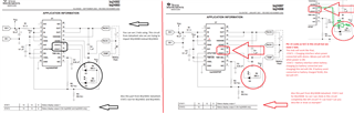
We are using BQ24002PWP IC now. But we are trying to change it with the BQ24008PWP. We are using completely same circuits for this 2 ICs. We have 2 LEDs, one for POWER and one for STATUS. Power LED works when power is ON, not about with battery connected or not. Status LED works from battery connected until battery charging then Status LED goes OFF. The circuit is normally working with BQ24002 we have not a problem about it. But when im connecting BQ24008 instead of BQ24002 Status LED is working before connect to battery. We want to use 2 LED like BQ24002 Application Information on BQ24008. But we could not find how to import it.

Please, keep in touch.

Thank you.

  • Hello

    Do you have a schematic of the current LED configuration that you are using with BQ24002 that you want to reuse with BQ24008?

  • Hello

    You can see our schematic below the writing.

    I want to give some details about projects. We are using J2 and J5 to connecting LEDs which one is green and the other is red. Red LED just for seeing when battery charges. Before connecting battery and after battery charged Red LED goes off. Green LED for POWER interface to see if charger connected electricity or not.

    R4 = 10kΩ

    R5 = 10.97kΩ  => we are ensuring that with 2 serial resistors like that => R5 = (10.kΩ + 0.47kΩ)

    In datasheet CR Pin values are like that,

    CR Min=2.816V   Typ=2.85V   Max=2.88V

    In datasheet APG/THM Pin values are like that,

    APG/THM Min=1.48V   Typ=1.498V   Max=1.515V

    Our CR and APG/THM Results which measured are like that,

    CR -> 2.851V

    APG/THM -> 1.49V

    So this schematic is for BQ24002. We want to completely preserve this schematic without BQ24002. We want to change BQ24002 with BQ24008  with this schematic.

    Thank you.

  • Hi 

    Thanks for the schematic.

    The BQ24002 will use open drain transistors for STAT1 / 2, pull down only.  While BQ24008 has a pull up / pull down transistor configuration.  

    Additional pull up of the BQ24008 may be causing issues.  

    Check the BQ24008 output from STAT pin that is causing the problems.  Is it toggling at a 1Hz rate for fault condition?

    Do you have the option to change the circuit, add external MOSFET?

  • Hİ again

    We are not using Stat1 and Stat2 as PWM. But I measured with oscilloscope so there was clean DC.

    I didnt understand why for MOSFETs? We are already using BQ24002 without them and it works.

    -I want to make sure we can use stat1 and stat2 with different leds right? Because we need a led to learn power is ON and other led for Battery charging. We need 2 leds. We dont want to use bicolor led or equivalent.

    -According to datasheet we should stat1 and stat2 with different leds. But how? Can you describe or draw it? Because there wasnt an example about it in datasheet.

    -I will try to describe this as visual.

  • Hi

    I tried some applications to eliminate ideas.

    -When battery connected BQ24002 measurements like that,

    Stat1(V)=0.251                          Power Led(V)=1.930

    Stat2(V)=1.278                          Status LED(V)=2.019

    -When battery NOT connected BQ24002 measurements like that,

    Stat1(V)=0.216                          Power Led(V)=1.929

    Stat2(V)=0                                 Status LED(V)=5.00

    -When battery connected BQ24008 measurements like that,

    Stat1(V)=0.257                          Power Led(V)=1.950

    Stat2(V)=4.926                          Status LED(V)=1.998

    -When battery NOT connected BQ24008 measurements like that,

    Stat1(V)=0.22                            Power Led(V)=1.949

    Stat2(V)=4.927                          Status LED(V)=1.965


    If I understand right, Stat1 and Stat2 in BQ24002 works open drain as default. Also BQ24008's Stat1 works like open drain as default but BQ24008's Stat2 not work like open drain as default. So how can I set Stat2 as like open drain if I can? Im still exploring..

    Thank you from now.

  • Hi Anil,

    I wasn't aware there was an active thread already. To prevent duplicate answers between Bill and I, let me answer here. I will close the other one.

    I pulled up a schematic we have and it shows the following:

    so I believe your schematic is fine. Can you provide a waveform for the STAT2 pin, STAT1 pin, and battery voltage?

    Best Regards,

    Anthony Pham

  • I measured what you said.
    The results like tihs,

    Measured with multimeter when battery not connected,
    Stat1 = 255mV
    Stat2 = 4.81V

    Measured with oscilloscope when battery not connected,
    Stat1 = 120mV
    Stat2 = 3.92V

    Measured with multimeter when battery connected,
    Stat1 = 225mV
    Stat2 = 4.82V

    Measured with oscilloscope when battery connected,
    Stat1 = 136mV
    Stat2 = 3.92V

    Battery voltage in multimeter
    4.087V

    Battery voltage in oscilloscope
    4.08V (like a straight line / pure dc)


    Also i already examined SLUU083 and SLU113.
    Oscilloscope results are clean DC on the screen.

    Now im trying to TMR_SEL's 6Hr form because circuit didnt cut when battery %100 charged. (luckily have a little BMS on the battery pack.)

    So problem 1- Auto cut doesnt work / why? / how to fix?   2- Still LED2 is not working .

    Thank you.

  • Hi Anil,

    Excellent to hear that you've already examined the two documents.

    If the timer is not stopping, then there may be a fault occurring. I did see that bill had asked about the APG/THERM voltage and it is close to the upper threshold. Is the battery charge current also clean? Can you provide this waveform?

    Best Regards,

    Anthony Pham

  • Hi again

    Im still using R4 as 10k but changed R5 with 10.97k (10.5 + 0.47k). I wrote it.
    And Im measuring with multimeter APG/THM as 1.491V.
    I think its not close enough to become a problem. Accually its pretty good value.

    Multimeter Measuring Results

    APG/THM - 1.491V
    CR - 2.855V
    STAT1 - 0.255V
    STAT2 - 4.917V
    OUT - 4.119V

    Oscilloscope Measuring Results

    APG/THM - 1.42-1.46-1.52 (ΔV=0.04)
    CR - 2.82-2.86-2.88 (ΔV=0.04)
    STAT1 - 0.252
    STAT2 - 4.9V
    OUT - 4.2V

    Also the circuit is which im using already work as BQ24002 Charger's circuit.
    So BQ24002 and BQ24008's values are same.
    APG/THM Seems have problem but i just take BQ24002 and change it with BQ24008.
    So shouldn't it work?

    I tried 11250ohm resistor but same result.

    Also i will add oscilloscope screens that i use R4=10k and R5=10.97k

  • Hi!

    I have a different result but I've only seen it once for 5 mins. I will try to send videos if the internet allows. I think that was pwm so what should i do now?


  • Hi Anil,

    Can you share what the waveforms are? What is CH1?

    Best Regards,

    Anthony Pham

  • The square waves are stat1 pin waveforms. Others not connected.

  • HI Anil,

    This lo oks like the behavior of the BQ24007. Can you confirm the IC markings on the device?

    Best Regards,

    Anthony Pham