Hi Team,
We have implemented the New DRV103H driver IC for operating the Solenoids (24V DC/1A continuous) in our product to replace the DRV101 (Obsoleted). The design is developed as per datasheet recommended and below are the set parameters for the IC.
Parameters:
1. Input Control Voltage to IC: 5V DC(0 or 1)
2. Supply voltage: 24V DC
3. IC driving: Low side driven
4. PWM Resistor: 110K Ohm (For 30% Duty cycle)
5. Frequency Resistor: 215K Ohm (For 24KHz)
6. Delay Capacitor: 330nF (For 330uSec initial Delay)

ISSUE OBSERVED DURING TESTING:
1. First we provided the supply voltage (24V) to IC and check if there is any short.
2. Later, we provided the control input voltage to check the PWM output from out pin.
3. Initially the delay time is observed as per calculation and could witnessed few PWM signals.
4. After few sec (approx 30sec), the IC didnt provide PWM signal and the output pin was in continuous mode
5. Later we removed the daughter PCB from main PCB and repeated the test separately by powering the IC and control input voltage.
6. At that time, we could be able to see the PWM signal continuously, and solenoid also connected across the diode (24V & output 0V)
7. But the IC produce more heat and the heat does not able to dissipate even we provided 4-layer PCB copper pouring for better heat dissipation.
8. The IC exhibits more than +85Deg C in ambient temperature of +25Deg C
9. But as per datasheet, the temperature rise calculated is not matched with the practical data. Also, we loaded the IC only 250mA in PWM mode (1A in continuous mode)
10. If we removed the Solenoid load and tested in open condition, even though the IC generates more heat when PWM output is ON completely.
11. Also, we replaced the IC DRV103U and repeated the same test, the IC produce the distorted PWM waveforms and IC becomes more hotter (>+85Deg C) than the DRV103H
Below are the Gerber images and waveforms provided for your reference. Kindly check the clarification points and suggest the solution. If the DRV103 is not capable, please suggest the new alternate IC for our existing part (DRV101) used in product currently.
1. Initial condition:
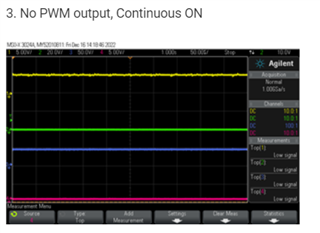
Yellow: Status Flag
Green: Output
Blue: Input
Pink: NC

2. Ton is Higher: (theoretical: 28.9uS for 30%DC, 24KHz)

3. No PWM output, Continuous ON

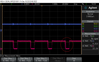
4. Driver IC tested separately and output is working with ringings:
5. Temperature Data:


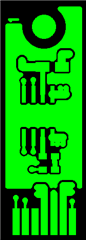
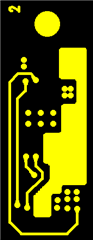
Gerber:
Top:
Inner layer:1
Inner Layer-2

Bottom
Clarification Required:
1. We like to know whether the DRV103H is capable to support 24V/1.5A(continuous) to load the Solenoid coil.
2. The power Pad can be connected to Ground signal. (In our current design, we isolated the power pad as per datasheet suggested)
3. The copper thickness mentioned in the PCB details need to be increased.
4. Any suggestion on the layout routing.
5.330nF capacitor is connected in the main PCB (The above testing are performed by assembling the delay cap near to the delay pin soldered)
6. Why the IC is heating when PWM signal output is ON.
7. The above IC parameters are set as per the existing DRV101 IC design. Is it required to change any parameters?
8. The Ton+Toff time is correct, but why Ton time is not matched with theoretical data.
9. Why ringing is produced in the PWM signal. Refer the above waveforms marking.