This thread has been locked.

If you have a related question, please click the "Ask a related question" button in the top right corner. The newly created question will be automatically linked to this question.

LM5023: About COMP pin function

Part Number: LM5023
Other Parts Discussed in Thread: UCC28740, , TL431

Hi team, 

I'm confuse about the function of COMP pin. I learned from the function of COMP is to compare it with CS signal to generate PWM signal. But I don't understand what the COMP signal is.

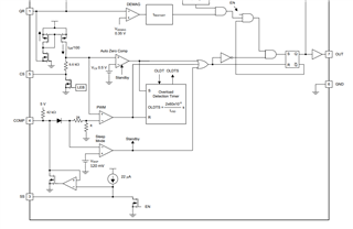
As datasheet desribing about COMP (green line part):

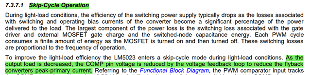
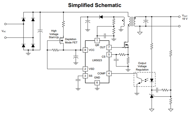
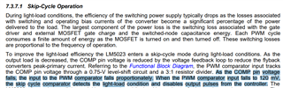
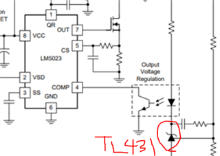
How does COMP pin work specifically?  Could u please kindly clarify this simplified schematic about the opto part ? How does COMP voltage reduce with decreasing load?

Thanks & best regards

Victoria

  • Hi Victoria,

    With the functional block diagram given on section 7.2

    When at light load (little output load current), COMP pin detects the secondary side light load through the opto (voltage feedback loop).  

    For how does an optocoupler work, it takes secondary side incoming signal (current) and output it to primary side as voltage. (more info can be found online)

    The highlighted part on the picture above corresponds with the spec V(skip)=120mV shown below.

    From the block diagram (first pic) you can see that there is a sleep mode comparator with cathode connected to COMP pin and anode connected to VSKIP 120mV then to ground. If COMP is below 120mV, it goes to standby mode and informs auto zero comparator to disable pulses outputting from the OUT pin.

    Thanks.

  • Hi Claire:

    Thanks for your detailed and patient reply. You made it clearer about the function COMP pin at light load.

    1.

    COMP pin detects the secondary side light load through the opto (voltage feedback loop)

    Could u please let me know where is the reference voltage in voltage loop? Does COMP represent output voltage condition?

    I would like to ask how COMP can reflect the condition of load. Does COMP voltage increase with a increasing load current?

    2.

    For how does an optocoupler work, it takes secondary side incoming signal (current) and output it to primary side as voltage

    About this part, I'm confused about what information does COMP sample? Does COMP voltage changes proportionally with different load current?

    3.

    I also would like to ask about UCC28740, I notice there is a FB pin. Does it have same function as the COMP pin in LM5023?

    Looking forward to your reply.

    Thanks and best regards,

    Victoria

  • Hi Victoria,

    From this picture, the red box indicates COMP pin and the components within the controller connected to COMP pin. (Basically COMP pin is connected to opto pin 4)

    When output is no load (Iout = 0), TL431(Shunt regulator) FB pin gets pulled high to Vout, since Vout is greater than Vref (2.5V) in TL431, current  flows from Vout to R bias to opto then to GND. Opto at the primary side provides current and pulls down COMP pin voltage (Vcomp originally was Vcc and got pulled down to Vcc - IR). 

    When output is full load, TL431 FB pin gets pulled down (Vfb < Vref), no current flows through opto diode, therefore no current flows through opto primary side, COMP pin voltage gets pulled high to VCC.

    UCC28740 FB pin is similar function as COMP pin in LM5023.

    For more information you can read this document from TI: www.ti.com/.../slvaf37.pdf