Hello,
I am using the TPS92515HV with analog dimming and shunt FET dimming at 3kHz to prevent flicker per IEEE std.
The analog dimming is used to dim higher current, in occurence from 100% to 25%, and the shunt fet dimming is used to dim from 25% to 0%.
This configuration makes this driver ideal for very high contrast applications.
My problem occurs in shunt FET dimming solely.
Since the shunt FET PWM from the microcontroler and the TPS92515 are not synchronized, the mean value of the LED current is statistically proportional to the duty cycle.
However, when I use a very fine tuning of the shunt FET PWM duty cycle, we can see that the mean current vary at some point, creating "dips".
Here is the mean current of the LED against the 16bit counter value of the shunt PWM output.
There is one measure at each 10increments; dips repeats themselve consistently.

The problem seems to be that the off-timer synchronize itself with the shunt FET PWM.
Thus, the current during each "un-shunt" cycle is the same instead of varying.
Here is the LED current with infinite hysteresis outside of a dip.
We can see that the current always varies :
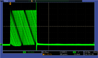
Here is the inductor current outside of a dip.
We can see that there is no repeating pattern.
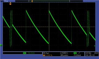
Here is the LED current with infinite hysteresis inside of a dip.
We can see that it is always the same at each "un-shunt" cycle :
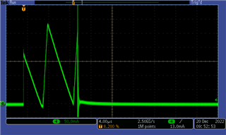
Here is the inductor current inside of a dip.
We can see that there is a repeating sequence.
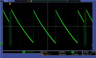
Sometimes, the sequence takes more than one shunt cycle to repeat.
This is where flicker is most seen.
Here is an example where the synchronization happens at each two cycles.
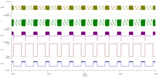
LED current in green, and COFF pin in yellow.
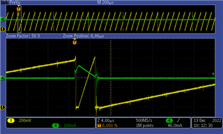
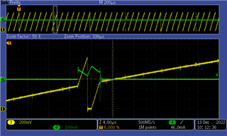
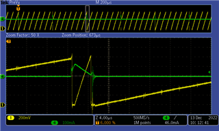
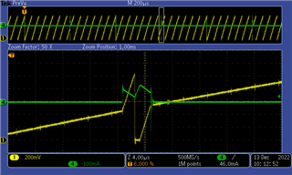
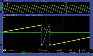
I believe this synchronization is inerent to the system and cannot be removed; there will always be a pulse width that perflectly match the limit cycle.
We tried modulating the duty-cycle with a mean value centered on the desired value, but there was still synchronisation at some point.
I would like to have the opinion of an expert in shunt FET dimming, maybe i do not understand the problem correctly.
Roff1 and Roff2 are perfectly matched to have the same current ripple when the LED are shunted or not.
I tried with different values of Roff2 to validate the effect of current ripple while shunted to no avail.
Anyone else stumbled upon this issue?
Any advice or rule to follow to prevent this from happening ?
Schematics available on demands throught email.
Thank you,
Philippe


