This thread has been locked.

If you have a related question, please click the "Ask a related question" button in the top right corner. The newly created question will be automatically linked to this question.

Help me understand negative current measurements

Part Number: INA260

I am using an INA260 in an application for power management. I have read the spec sheet, and some of the application notes, and done some experimentation and coding. I would like to make measurements on negative current flow, but I am unclear how this must be done: 

In para 8.5.1 the following statement appears:

Because the INA260 supports current measurements in either direction, the returned value for negative currents (currents flowing from IN- to IN+) is represented in two's complement format. Returned values for power will always be positive even when the current is negative.

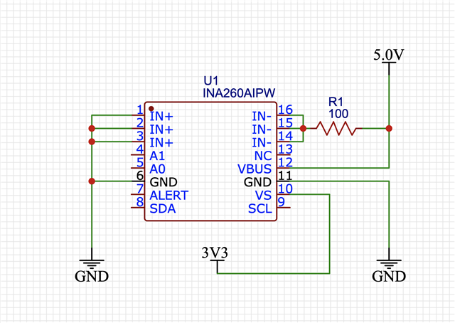
In Figure 38. Typical Circuit Configuration, INA260: 

For current to flow from IN- to IN+, IN- must be biased above IN+. Since the Power Supply connection at IN+ seems to be specified within limits of 0 volts to 36 volts, this would mean that a positive voltage would have to be connected to IN- in order to create the negative current flow described above.

In para 8.6.3, Bus Voltage Register

Para 8.6.3 states Vbus is the voltage measured, and that Vbus is always positive.  However, when current is negative (flowing from IN- to IN+), the measured voltage across the shunt is negative. This is where I get lost!! The switching action of the ADC seems to be that it alternately measures shunt voltage drop (related to current) and Vbus-Gnd (used in the Power calculation. But nowhere does it say that Vbus must be connected to the + side of the power supply connected to IN-. 

Finally, the questions:

Have I sussed this correctly? In other words:  For negative current and power measurements to be valid, is it necessary that Vbus be connected to IN- ?? If not, can you please provide a complete explanation or schematic on how to connect for a negative current measurement?

Also - as a point of curiosity, wouldn't it have been easier to allow Vbus to also take on negative values?

Thanks for your help.

Happy Holidays!

two's complement

  • Hello,

    I can see your confusion. Let me try and clarify. If you are measuring on the high side of the load this will most likely be on the IN+ pin. If on the low side of the load it will most likely be on the positive side of the load.

    When measuring negative current and the Vbus pin is connected to the IN+ pin the Vbus will be lower by the voltage dropped by the shunt resistor.

    Are you placing the INA in high-side or low-side sensing? Are you only interested in the negative current?

    If you provide a schematic of your circuit we could further assist you on how to connect the INA260 Vbus pin.

    Regards,

    Cas

  • Here's a screenshot of a schematic...

    Well - that would be great... I've made the screenshot, but how do I get it into a reply?? Insert has no file selector in the insert menu???? I've wasted 20 minutes on this - how does this thing work??

  • OK - finally figured it out! The "Insert" dropdown threw me off completely!

    Anyway... This how I've got my INA260 wired. It seems to be working - in the sense that I am able to measure a negative current. But I remain puzzled, in part because I do not see why this was necessary. I had to give some thought on how to wire this simple circuit to yield a "negative current", and of course TI's spec sheet provides the obvious example (positive current).

    My question seems to come down to this: Can you show me an example of a measurement case which requires one to measure negative current? I can't... And since the data in the Current Register (01h) is two's complement (which requires different handling in my application code), I'm curious to know what's behind the design choice made by TI.

  • Hello,

    Yes providing a higher potential on the IN- side and a lower potential on the IN+ side will result in "negative current" flow. I guess I did not understand exactly what you are confused about.

    If you are looking for a use case of negative current you can think of a battery application where the we must measure the charging and discharging current. You can call whichever way negative current and the other positive current. But the main issue becomes that you will need to measure current going in both directions therefore we need to measure "negative current".

    Hope this helps. If not please reply.

    Regards,

    Cas

  • Hmmm... Yes, current would be flowing in both directions, and that would be a great application. But how would you bias Vbus for this application? Is there a schematic for that? Let me think on this a bit...

  • Hello,

    The Vbus can be placed either on the IN- or IN+ pin. When the current is bidirectional you will most likely measure on the high side of the load. 

    Here the INA IN+ pin will be towards the circuit/charger and IN- pin will be towards the battery positive terminal.

    If placed in the IN+ pin:

    Positive current: Current from external source to batteries. The Vbus will be at the potential of the external source.

    Negative current: Current from batteries to circuit. The Vbus will be the battery potential minus the Vshunt drop.

    If placed in the IN- pin:

    Positive current: Current from external source to batteries. The Vbus will be the external potential minus the Vshunt drop.

    Negative current: Current from batteries to circuit. The Vbus will be at the potential of the battery source.

    Either way the voltage at Vbus will be similar.

    If you want to measure low side current and still measure power you can place the Vbus pin at the positive side of the load.

    Regards,

    Cas