This thread has been locked.

If you have a related question, please click the "Ask a related question" button in the top right corner. The newly created question will be automatically linked to this question.

Power switch with reverse current protection

Other Parts Discussed in Thread: TPS22917, TPS22917EVM

Hi,

Need your advice regarding power switch with reverse current protection.

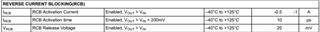
After the power switch enabled, during a permitted state, (when Vin > Vout for example), if the situation changed and Vout becomes greater than Vin, the reverse current will be blocked.

Do you have a good candidate for such requirement?

Thank you very much!

Erez.

  • Hello Erez,

    What are your input requirements and expected load current/inrush current?

    TPS22916 has always-enabled reverse current blocking. It also has versions that are active LOW/HIGH with and without QOD.

    Regards,

    Kalin Burnside

  • Thank you Kalin for your response!

    Continuance forward current = 0.5A.

    Inrush current resulting of C load = ~22uF.

    Input voltage - up to 6V.

    (Unexpected) output voltage to block – up to 6V.

    Not BGA package.

    And of course, block any (unexpected) reverse current, even during forward current flow when suddenly the output voltage becomes greater than the input voltage.

    Regards,

    Erez

  • Hello Erez,

    TPS22917 has always-enabled RCB, SOT-23 package, and output slew-rate control to minimize inrush current. The ABS max of the output pin is 6V.

    The way reverse current protection works in our devices is it requires a voltage drop from Vout to Vin > VRCB to enable RCB. This means you can have activation currents as seen in the specifications below(-1A worst case):

    Regards,

    Kalin Burnside

  • Thank you Kalin!

    we will try this power switch.

    I will order the evaluation board and I will test it.

    Thanks again!

    Erez.

  • Hi Kalin,
    we have got the TPS22917 evaluation board and we tested it.
    It seems that only when the power switch is disabled it protects from reverse current.
    When it is enabled it doesn't do the job...
    If Vout > Vin, than Vin is forced to Vout value.
    Regard,
    Erez.

  • Hello Erez,

    Could you please explain your exact test setup with the voltage applied to Vout and to Vin?

    Regards,

    Kalin Burnside

  • Hi Kalin,
    We would like to prevent a (mistakenly) connection of voltage source on buck-boost output (buck boost output = 5V in our case).
    After the buck-boost output we are using power switch with reverse current protection, but the reverse current protection works only if the power switch is disabled.
    If the power switch is enabled and then if mistakenly someone connects external power source (5.5V for example instead of simple resistance load) - we would like that a reverse current will be prevented even if the power switch enabled.

    Thanks,

    Erez

  • Hello Erez,

    Thank you for explaining the application you're using this in. Reverse current blocking requires a drop of about 25 mV typical from Vout to Vin for it to engage. This can result in an activation current in the reverse direction until the 25mV drop across the FET has been achieved. 5.5V on the output and 5V on the input should be enough to cause RCB to engage. Can you explain how you're testing this in more details?

    Regards,

    Kalin Burnside

  • Hi Kalin,
    Thank you for your reply!
    As mentioned, the topology is:
    Buck-boost -> Power switch -> Resistive load, or alternatively (forbidden external) Voltage source.
    Test procces:
    1. Buck boost wakes up. its output voltage = V(buck-boost) = 5V.
    2. Power switch enabled over resistive load; Vout = 5V (as expected).
    3. External strong source of 5.5V is applied intentionally over the same resistive load (while the power switch is still enabled).
    4. The buck-boost output voltage becomes 5.5V (instead of staying 5V).
    Regards,
    Erez.

  • Hello Erez,

    I will test this in the lab today with our EVM and let you know my findings. It's possible it could be a supply constraint. Do you have scope shots you can provide?

    Regards,

    Kalin Burnside

  • Hi Kalin,

    Currently I have no scope pictures, but the behavior is pretty clear.
    Please let me know regarding your findings...
    Thank you very much!

    Erez

  • Hello Erez,

    I've ran the test on the TPS22917EVM with 5V on input, 5.5V on the output after the device was already on and saw the RCB enable. Please see the scope shot below:

    I'm not sure if this is a supply constraint that you have, or measurement issue, but the device performs properly on our test setup. Perhaps testing another EVM on your end would help rule out a damaged device?

    Regards,

    Kalin Burnside

  • Hi Kalin,
    Your support is very appreciated!
    Maybe we will buy a new power switch, and try to replace it on the EVM.
    I will update you when I will back to this set-up...
    Thank you very much!
    Erez.

  • Hello Erez,

    Were you able to test this on another EVM?

    Regards,

    Kalin Burnside

  • Hi Kalin,

    Thank you for your interest,
    We haven't yet tried another component.
    But we did repeat the test we had already done and there is indeed a problem here.
    We did it as described on the following steps:

    1. Powering up the buck boost converter (before the power switch).
    2. V(power switch In) = V(buck-boost out) =  5V.
    3. Power switch enable = 3.3V.
    4. V(power switch out) = 5V.
    5. V(power switch out) Forced to 5.5V => V(power switch In) = V(buck-boost out) = 5.4V – Fail.
    6. Power switch disabled manually (using JP1) = 0V => V(power switch In) = (back to) 5V – Ok.

    The component appears to be functioning except for reverse current blocking (when enabled).
    If we will try new component I will let you know.

    Thank you very much!

    Erez

  • Hello Erez,

    That would be great if you could let me know how the test results are on a new device. Also, when measuring the 5.4V on the input- is this for an extended duration/permanent until you turn the device off? Are you able to measure the reverse current at all- even if it’s just from the external source forcing it to 5.5V?

    Regards,

    Kalin Burnside

  • Hi Kalin,

    5.4V on the Input was until I turned off the device (10-20 seconds).
    The buck boost converter uses us for on-board additional loads, from what I remembered, the reverse current was around ~300mA (I saw it on the lab power supply display).
    Anyway, In the meantime, I was instructed to suspend dealing with this matter.
    I'll see if I will get a chance to back to it and make some additional tests, I will update you...

    Thank you very much!

    Erez