Hi Experts,
Good day! Our customer need your expertise on their design. Kindly please help to verify. Here is the full details below.
we are planning on using the LMR14050QDPRRQ1 to carry out the following: Convert 12-24VDC to 5VDC 5A Output.
In order to properly operate the LMR14050QDPRRQ1, I consulted the data sheet (Section 8.2), WEBENCH and the LMR14050SEVM User Guide Schematic. I will be going through each component that the datasheet mentions and I'd like you to verify that the design is correct.
1. Output Voltage Set-Point
We adhered to the 100kOhm and 17.8kOhm as mentioned in the datasheet, but WEBENCH uses 68kOhm and 12kOhm. Would this make a difference? Furthermore what is Cff exactly? Since it is not mentioned in the datasheet nor in the LMR14050SEVM. Cff also seems to change when changing the start-up time.
2. Switching Frequency
The datasheet uses 300kHz whilst the EVK uses 400kHz. WEBENCH suggested 1MHz by default however we have a SIM Card Interface running at 5MHz and we need to avoid harmonics of these order (2, 3, 5, 7). Thus, which switching frequency would you suggest? Will the efficiency be higher at higher switching frequencies for example?
3. Output Inductor Selection
The datasheet suggests 8.2uH and so does WEBENCH (8uH). The LMR14050SEVM uses 5.5uH however (because of the 400kHz switching frequency). Based on Equation 10 in the datasheet this would need to be recalculated as per the switching frequency however so we should tackle this point after confirming the switching frequency.
4. Output Capacitor Selection
The datasheet suggests 4 x 47uF whilst WEBENCH suggests 2 x 20SVPF390M (390uF). The LMR14050SEVM uses 2 x 100uF and 10uF. Again this selection depends somewhat on Point 2 (the switching frequency). However feel free to suggest your preference. For example I am inclined to choose 2 x 20SVPF390M to better handle large current spikes.
5. Schottky Diode Selection
The LMR14050SEVM mentions the PDS760 however we might opt for the V8PAM10S-M3/I. Would the V8PAM10S-M3/I be a good option?
6. Input Capacitor Selection
The datasheet suggests 2 x 2.2uF capacitors however WEBENCH uses 39uF and the LMR14050SEVM uses 56uF, 4.7uF, 4.7uF, 220nF. I am inclined to use the configuration from the LMR14050SEVM since again it might handle current spikes better. What do you think?
7. Bootstrap Capacitor Selection
This is fine - all designs use 100nF.
8. Soft-start Capacitor Selection
WEBENCH and the LMR14050SEVM suggest 20-22nF but the LMR14050QDPRRQ1 supports a maximum of 4.7nF. Thus we should use 4.7nF in this case, correct?
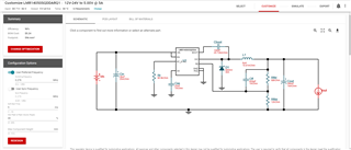
Attached below please find the screenshot of WEBENCH as reference. I kindly ask you to reply in point-form as per my request in order to keep everything in order and not loose track of things.

Best regards,
Jonathan

