Other Parts Discussed in Thread: UCC28070, UCC27517, PFCLLCSREVM034
Hello,
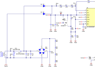
I am using UCC256404 in my design. I noticed that the chip is running a little hot. Thermal imaging shows that the case temperature of the chip is about 60C at ambient room temperature. I measured the VCC supply current and I am getting about 90mA - 100mA. The datasheet indicates that the ICC run current is about 2.5mA or so. So I would like to check whether is this expected.
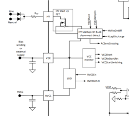
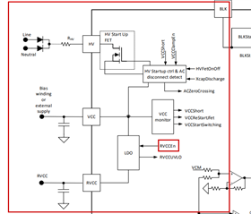
I also have another question with regards to the RVCC regulated 13V supply. From the block diagram in the datasheet, it is shown that there is an internal LDO that regulate the RVCC from the HV input pin. HV input is coming from a rectified AC line. If the AC line is 240VAC, this would also mean that there is big delta voltage between the LDO input and output. If RVCC current is high (~100mA), wouldn't this cause a big power dissipation within the chip itself?
Lastly, is there any relationship between the RVCC current to the VCC current? Example, if RVCC is pulling 100mA, VCC current would also increase accordingly. Does not seem so in the datasheet but would like to confirm this.
Thank you in advance.
Regards,
Jason