This thread has been locked.

If you have a related question, please click the "Ask a related question" button in the top right corner. The newly created question will be automatically linked to this question.

BQ76940: Bq76940 ntc measurement is wrong at startup

Part Number: BQ76940

Hello,

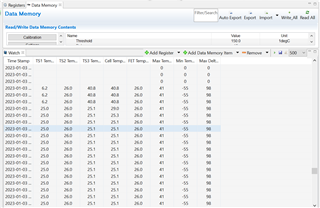
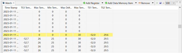
I'm using BQ76940 and BQ78350-r2 IC for BMS design. I'm using three external ntc. In the above picture, TS3 temperature is read 40.8 for 1.5sec then it fixes. What is the reason of this? After the start up meauserement works well. 


Thanks for support,
Best Regards
  • Hi Korcan,

    For the BQ76940, the thermistors are measured every 2 seconds, so this might explain why you are seeing the wrong value initially. 

    Best regards,

    Matt

  • Hi Matt,

    This case is observing only first wake up from shutdown mode. We believe it's causing from wrong value read at the first initialization.

  • Hi Ali,

    The first BQ76940 temperature measurement will not take place for 2 seconds after waking from Shutdown. Since the step size in your Watch window is 500ms, it looks like you are seeing this 2s delay. The measurement occurs with a 2s period.

    Regards,

    Matt

  • Hi Matt,

    Actually our problem is, TS3 is reading 40.8 after waking from shutdown. This causes PF state. Also this value is wrotten in Lifetime data. How do we get it the correct temperature(25C at room temperature like TS2 value) at the first initilization?

    In the attachment files, Yellow (1) signal is TS1 pin, blue signal(2) is TS2 pin and green (4) signal is TS3 pin voltage of IC.  Ts3 pin voltage is high 1.8sec after the TS1 and TS2 pin voltage.  Could this be why TS3 misread?


    Best Regards,

    KT

    Regards,

    Korcan

  • Hi Korcan,

    It seems like the top cell group is starting up slower than the bottom two cell groups. Can you share your schematic so I can see if there are any potential issues?

    Regards,

    Matt

  • Hi Matt,

    I'm sorry, I can't share shematic according to company policy. Could you tell me which I should measure IC pin  to see if the problem is potential issues?

    Thanks for support.

    Regards,
    KT
  • Hi KT,

    It's a little difficult to debug without more info. On the TS pins, can you let me know what is connected to these pins - is it only the thermistor or do you have additional components? 

    Since you cannot share the schematic, it may also be good to watch this video to see if there are any issues you might notice: https://training.ti.com/how-create-schematic-bq76920-bq76930-and-bq76940 

    Best regards,

    Matt

  • Hi Matt,

    I watched the video which you send. I used in external thermistor (10k)TS1,TS2,TS3 in design.  My design is the same as the design in the video but only difrerence about TS pin is  VC5x is  connected the NMOS gate pin with 100k. Is this affect the measurement?

    Thanks for support,

    Regards,

    KT

  • Hi Korcan,

    100k for the gate resistor should be okay. See this TI Reference Design which also uses the same value: https://www.ti.com/tool/TIDA-00449 

    Matt

  • Hi Matt,

    If I take off the external ntc connecter(TS1-TS3), Afe measures temperature values in the below picture. TS3 is 52.7 and TS1 is 52. If the external ntc isn't connected, Do ts1 and ts3 have to be same value?  What is the diffrence (0.7C) between TS1 and TS3?

    Regard,

    KT

  • Hi Matt, 

    We realized a new situtation. In the below picture, Blue signal is measured with differantial probe between VC15x and CAP3 pin of IC. Yellow signal is measured with with differantial probe between VC10x and CAP2 pin of IC. Both signal voltage decreases 3.3V but  yellow signal has offset voltage even if the turn off the product. Before ossiloscope measures TS3 pin has offset voltage. Is this correct for referecence desgin? Thanks for support.

    Regard,

    KT

  • Hi Korcan,

    This is getting a little confusing - I am not sure why you are trying to measure temperature with no thermistors or pull-down resistors installed since the part is not designed to be used this way. 

    Each of these voltages should measure 3.3V (CAP1 - GND, CAP2 - VC5X, CAP3 - VC10X). Are you seeing 3.3V for each of these measurements?

    Regards,

    Matt

  • Hi Matt, 

    Hi Matt, I measured the points and saw 3.3V as you said. I worked with the cell simulator and wanted to see what would happen when I unplugged the ntc connector. Does TS1 and TS3 have to measure the same value in this case or not?  Design is the same at reference design. Difference is, regout uses Gauge IC VCC and is connected a  few mosfet gate. Is this affect ntc measurement?

    Regards,

    KT

  • REGOUT connecting to the Gauge IC is okay, and other circuits can be powered as long as you stay within the datasheet REGOUT current limit. 

    I am not sure what will happen when there is no thermistor or pull-down resistor on the TSn pins because this is not a valid configuration for the device.

    Regards,

    Matt

  • Hi Matt,

    In the below picture, green signal is TS3. There is no pulse at the beginnig of the signal but TS3 is showing 40.8C. TS1(yellow) and TS2(blue)  pulses at the same time. How is this possible? If the problem is voltage difference issue, TS3 pulses at the same time TS1 and TS2 but voltage level should be different according to TS1 and TS2.

    Regards,

    KT

  • Hi Matt,

    I want to ask another question. Could you help me for this issue? Is BQ79600 compatible with BQ76940? If answer is not ok, Could you suggest IC P/N which  uses in BMU compatible with BQ76940 for energy storage systems?

    Thanks for support,

    Regards,

    KT

  • Hi KT,

    I answered the BQ79600 question in your other thread. BQ79600 is not compatible with BQ76940.

    Regarding the TS3 pulse question, I am not sure I understand what you are asking. The startup time between each cell group will be different - the temperature reading should only occur at around 2 seconds after startup. This is difficult to debug without a schematic - maybe you can share it privately (you can send an E2E connection request to me and share it in a private message)?

    Matt

  • Hi Matt,

    Yes, you are right. It is diffcult to solve this bug without schematic. We will consider to send schematic. In this picture, TS3(green) voltage level is zero at startup. Moreover at startup, there is no pulse like TS1 and TS2. So if the voltage level is zero, how TS3 is reading temperature value?Also offset voltage is zero. 

    Regards,

    KT

  • Hi KT,

    How do you know that TS3 is reading a value at this point? Do you have the oscilloscope synced to the register readings somehow? Is it possible the TS3 temperature reading is from the next pulse?

    Matt

  • Hi Matt,

    Yellow signal is TS1. There is a button for on/off process like in your design. After start up pulse of TS3 is reading three times 40,8C in 500ms intervals. I measured distance between TS2 and TS3 pulse. The distance is 1.8ms. I tested  different room temperature, and TS3 is still reading 40.8C at start up. If the TS3 is reading wrong value, why is still reading 40,8C at different room temperature? Another question if I send schematic in related part afe and external balance, is that enough for you. Regout is connected a few another section.

    Regards,

    KT

  • The schematic for the AFE should be enough.