Hello,
How can I calculate Inrsuh-Curent for TPS7A78 and steady state current? I want to know and calculate the minimum power rating and energy rating for the series Resistor Rs.
Can somebody help me?
This thread has been locked.
If you have a related question, please click the "Ask a related question" button in the top right corner. The newly created question will be automatically linked to this question.
Hello,
How can I calculate Inrsuh-Curent for TPS7A78 and steady state current? I want to know and calculate the minimum power rating and energy rating for the series Resistor Rs.
Can somebody help me?
Hi Christoph,
One quick way to do this analysis is to use the SIMPLIS model available on TI.com to simulate the inrush. This way you can quickly modify your Rs and other circuitry between the AC input and the TPS7A78, and see the associated inrush. Let me know if this method will not work for you.
Thanks,
Stephen
Hi Stephen,
I made some simulations for inrush current and I also did some measurements.
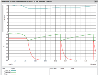
In simulation the output Voltage of 3.3V and V_LDO IN is shutting down, while in real application everything is fine. Can you explain why?
In both cases VSCIN is going below 14.5 Volts
Simulation:

real measurement:

Hi Christoph,
Please give me up to 2 business days to review and respond.
Thanks,
Stephen
Hi Christoph,
In the simulation the UVLO is being tripped (falling is 3.5V). The SCIN is divided by 4 so if it falls below 14V this could be an issue. 3.5V is the "max" value but there is some statistical variation here.

You should be seeing about 4V with some ripple on LDO_In, but I cannot tell from your hardware measurement if you have 4V or something else (3.2? That can't be right if you have 3.3V on the output...).

It looks like your SCIN voltage is drooping during inrush. Do you have a large capacitance on SCIN, such as a 220uF aluminum electrolytic? If your SCIN and LDO_In capacitors are reasonably large, we might need to look at your series AC+ resistors to see if they are too large. A schematic would be very helpful if you can share it.
Thanks,
Stephen
Hi Stephen,
sorry it took some time to verify and I had some vaccation....
The SCIN is droping during inrush, because Im using it to switch a relay. So this is okay. But I want to avoid, that LDO_OUT is shutting down.
So I like the behaviour in my measurement. But Im not sure if it is a safe behaviour, because simulations showed a different behaviour
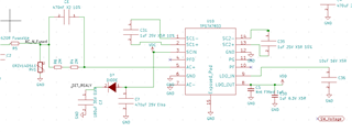
Cap @ SCIN = 470uF + 470uF via Diode
R_IN = 620R
Cs = 470nF
C_LDO_IN = 10uF
here is a Screenshot of the schematic:
Additional Information:
-> SImulation and measurement was taken with 270nF, to consider aging of Cs
-> Relay is like a 135R load on SET_Relay for 15ms
Hey Christoph,
I just received your updates. We are about done for the week here and Monday is a holiday for us. So the earliest I can dig into the new information will be Tuesday afternoon or more likely Wednesday of next week. But I will get to it and I'll reply back when I have feedback.
Thanks,
Stephen
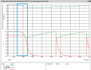
The simulation has SCIN drooping during the relay event. LDO_IN is unable to maintain headroom to the output, and the LDO_OUT enters dropout. At 0.865 seconds into the simulation the 3.5V UVLO is tripped, turning off the LDO. 3.5V is the "worst case" trip that you can experience - most of the time in actual hardware this will be lower. A typical value for UVLO trip is closer to 3.3V (that's not in the datasheet, but you can measure it using an EVM and supplying DC to the SCIN pin). Your test data is statistically closer to typical operation than the simulations worst case operation. I don't have a statistical spread readily available for the UVLO trip point, but just be aware that once LDO_IN drops below 3.5V you may turn the LDO off until LDO_IN recovers.
I noticed that LDO_IN droops more in the simulation than the measurements. Perhaps there is a heavier load in the simulation than in actual hardware measurements? It's also possible that the simulation is doing something incorrect that I need to investigate further (see the blue boxed area below). Can you confirm the loads on LDO_IN, SCIN and LDO_OUT match between the simulation and hardware measurements?
In this image, SCIN seems to follow with the hardware measurements but LDO_IN drops (almost like SCIN_UVLO is tripped) and LDO_OUT is following expected behavior given the LDO_IN voltage.

Thanks,
Stephen