This thread has been locked.

If you have a related question, please click the "Ask a related question" button in the top right corner. The newly created question will be automatically linked to this question.

LM5030: LM5030 Internal gate driver specifications.

Part Number: LM5030

Good Day Sir/ Madam

For my push pull converter application I have selected LM5030 (VSSOP package).

The junction to ambient resistance is given as 158 degree c/W which I think is very high for my application. I wanted to do a power calculation (Power lost in the internal gate driver side ) to see whether temperature levels obtained is satisfactory (More concerned about the thermal shut down in the data sheet saying at 165 degree c .) .

Could you please provide me with the Rdson of the internal gate driver for doing my calculations?

Or any application note regarding the power calculations of the IC can also be fine.


Thank you

  • Hi,

    You do not need the Rdson of internal driver and actually the internal driver is a circuit cannot be described by Rdson.

    The internal driver power dissipation can be estimated by the voltage and the current into the driver (Vcc) to estimate the average power the IC has. You would need to your external MOSFET parameters to help your estimation.

  • Ok Thanks

    I want to get the power dissipated by the IC for driving the mosfet. The current to be driven is 0.3A. To drive this i want an estimate of how much power the IC would dissipate.

    Can you provide any power calculation related to the IC?

  • Hi,

    I believe what you mentioned 0.3A is the peak driving current. If so you need to calculate the current demanded to Vcc, you need to know fsw and your external MOSFET gate charge parameters. After you get the current then multiply it to Vcc to get the power.

    You can search internet to get the formulas how to calculate the driving power based on your fsw and MOSFET parameters.

  • Hi thanks my issue is resolved.

    I wanted to ask a different question so am putting it here as i am not able to post a question in the forum.

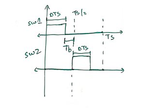
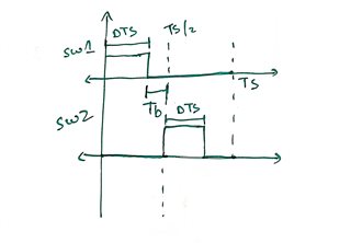
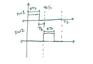
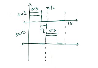
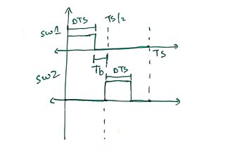
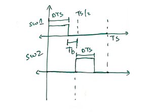
    My question is in the data sheet there is a specified dead band given (135ns).What is this value?  As in for different duty requirements the dead time required would be varied right? Could you brief on this how this works. I have attached a waveform as well for your reference . I want to know whether the Tb would be adjusted automatically.(in the graph)

    Thanks a lot .

    Sorry for the question being posted here .

  • Hi,

    Based on the datasheet, typical dead time is 135ns, and 85 to 185 ns across temperature range. These are fixed for duty at about 50%. For smaller duty the additional off time is due to the converter operation so not part of dead time setup. It is called off time instead of dead time.