This thread has been locked.

If you have a related question, please click the "Ask a related question" button in the top right corner. The newly created question will be automatically linked to this question.

UCC28056: Some questions about the formula in datasheet of UCC28056

Part Number: UCC28056

This is Skylar from South China team in charge of GREE and now I am in BU rotation in HVC as an AE.  Now I am learning the UCC28056 and I have some questions in the UCC28056 datasheet.

  1. how to get formula (2)?
  2. How to get formula (14) ?
  3. According to formula 17, Vinrmsmin2=(Kzc*Vff0fall)2/2 and how to understand such equality?
  4. Lbst1=(401*0.331)2/(1.1*2*165)*12.8*0.735/2=228uH which is a little different from 235uH.
  5. Also why is Lbst set as 200uH and how much should it be less than 235uH?2335.ucc28056.pdf
  • Hello Skylar, 

    Thank you for your interest in the UCC28056 PFC controller.

    1.  Formula (2) is simplified from formula (1), where Vin(α) is = Vin(θ).  I think the variable "α" was used by mistake, and should have been "θ".  
    In the text paragraph just below formula (1), it explains that the on-time Ton is held constant over the entire line cycle, so Ton(θ) = Ton for any angle θ. 
    So, Vin(θ) cancels on each side of equation (2) and the remaining expression is inverted to arrive at equation (2). 

    2.  Formula (14) (equation 14) is of the same form as equation (13).  In the specification table on page 8 of the datasheet, we see that Gff0 =1, so equation (13) can be written as RinEqMin0 = (2xLbst) / (Tonmax0 x Gff0).  This has the same form as equation (14).
    In general, the equivalent resistance for each of the line-feedforward levels can be found as RinEqMinx = (2xLbst) / (Tonmax0 x Gffx). 
    But actually only the RinEqMin for each the first two lowest levels of Gff are needed for design because these levels are where the peak currents are highest.  

    3.  Equation (15) uses the RinEqMin0 from eqn (13) to determine 110% of Poutmax (= PinMax).  PinMax is used in eqn (16) to find the boost inductance necessary to process this power.  In eqn (16) there is an implicit Gff0 term, but since Gff0 =1, it does not appear in the equation.   Eqn (17) is different from eqn (16) because it accounts for RinEqMin at the lower edge of the Gff1 level.  There is hysteresis in the level thresholds, so that the power level for moving from Gff1 down to Gff0 is lower than the power level for moving from Gff0 up to Gff1.  Using both eqns (16) and (17) for find the lowest Lbst ensures that Lbst is suitable to process the maximum power whether the input line voltage starts lowest and increases or starts higher and decreases. 

    4.  I agree with your calculation and I cannot explain how the datasheet arrives at 235uH.  I can only speculate that either one or more of the parameters may have had different values at the time that the application note was written, OR, the author made a small mistake in entering the numbers and did not double-check his result. 

    5.  That is a good question.  Since the text says that choosing a higher inductance value will not be able to deliver the full power, and we know that the boost inductor will have a +/- tolerance, I think a good choice is ( min(Lbst0, Lbst1) / +tolerance).  For example, if a magnetics vendor can hold +/-10% on an inductance around 230uH for the current level required, then Lbst = ( min(255uH, 235uH) / 1.10) = 213.6uH.  This can be rounded to 214uH or 213uH or 210uH for a "cleaner" number.  
    I'm not sure why the app-note chose 200uH, unless it was a "Standard" value that could be an off-the-shelf inductor.  (Next standard value of 220uH would be too high. ) 

    I hope this helps your understanding. 

    Regards,
    Ulrich

  • Hi Ulrich,

        Thanks for your detailed explanations which are really helpful. And could you pls answer other questions?

    1. In formular (1),  
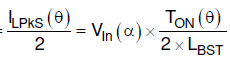
I could not figure out how the equation produces and is it because U=Ldi/dt?
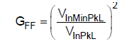
    2. Why does it have to have a fixed gain between COMP pin and Vin and how to deduce this formula (11) ?

  • Hello Skylar, 

    1.  Yes, formula (1) is a re-arrangement of the general formula U=Ldi/dt. 
    As specified in the text just above it, eqn (1) is based on ideal CrCM operation which means iL always starts at 0 and di goes from 0 to IlpkS(θ) for each switching cycle and dt = Ton(θ).  
    So rearranging terms in the middle of eqn (1) gives Vin(θ) = Lbst x IlpkS(θ) / Ton(θ).  

    But eqn (1) starts out relating the average cycle current to the average Vin over equivalent resistance at a specific point in the line cycle (θ), which is ILAvS(θ) = ... = Vin(θ) / RinEq. 

    2.  In the UCC28056, the gain between COMP and Vin is not fixed because Gffx has 8 levels from Gff0 to Gff7.  These 8 levels adjust the gain of the votlage loop in 8 discrete steps from low line to high line.  (Ideally, the gain should vary continuously, but here it is quantized to 8 levels.) 
    The purpose of the feedforward gain adjustments is to keep the overall voltage loop gain relatively constant across the input line range.

    Without Gff, there would be very high loop gain at high line (264Vac) and low loop gain at low line (~85Vac). 
    So for full power at low line, COMP = ~5V, but at high line, gain goes up and COMP would have to go down to <2V for the same full load power. 
    The change in gain with line actually follows the square of the max to min ratio. 
    So in the UCC28056, a quantized gain adjustment block is introduced that reduces loop gain by the inverse of the ratio squared.

    Hence, Gff0 = (VinMinPkL/VinPkL)^2 = 1 where VinPkL = VinMinPkL.  As Vin increases to the next range above VinMinPkL, Gff1 = (VinMinPkL/Vin1PkL)^2 = 0.735.  As Vin increases to the next range above Vin1PkL, Gff2 = (VinMinPkL/Vin2PkL)^2 = 0.541.  As Vin increases to the next range above Vin2PkL, Gff3 = (VinMinPkL/Vin3PkL)^2 = 0.398.  And so on, for Gff4, Gff5, Gff6, and Gff7.  These gain adjustment values are found in the Electrical Characteristics table on page 8.  Also on page 8 are the rising and falling threshold voltages for moving from one gain level to the next, either up or down. Note that there is hysteresis between the rising and falling thresholds to avoid chatter at a gain-level boundary.  
    A scaled representation of Vin is synthesized internally by processing the Ton and Toff times with respect to the total switching period as sensed each cycle at the ZCD/CS input. 

    Regards,
    Ulrich

  • Hi Ulrich,

        It's very nice of you and your description is of great help.

        Could you pls tell me why Gffx is divided into 8 levels and how it is divided?

        Also, I don't understand this sentence "Without Gff, there would be very high loop gain at high line (264Vac) and low loop gain at low line (~85Vac). ''

       Sincerely thanks for your help!

    Regards,

    Skylar

  • Hello Skylar, 

    I'm sorry I couldn't reply on your new questions today.  I'll get back to you as soon as I can. 

    Regards,
    Ulrich

  • Hi Ulrich,

        Thanks for your support! Looking forward to your reply.

    Regards,

    Skylar

  • Hello Skylar, 

    I think I'll answer why the loop gain varies from high line to low line first, then I think it'll make more sense about the quantized Gffx levels. 
    To avoid a lot of theoretical math, I'll describe the boost control operation more qualitatively.   

    The UCC28056 operates in critical conduction mode (CrCM) (also known as boundary mode (BM) and transition mode (TM)) which uses constant on-time to achieve PFC.  For a full power load, at the lowest input line voltage (say 85Vrms), COMP will be at its highest voltage (~5V) to drive the maximum on time. 
    Just consider the peak of the line: 85Vrms = 120Vpk.  For a given full load, input current is highest at the peak of the lowest line.  CrCM requires that Ipk of the inductor Lb = 2x the peak of the average ac line current.   Going forward, LL= lowline, and HL = highline. 

    The on-time to achieve that Ipk is tON_LL = (Ipk_LL * Lb) / Vinpk_LL and this on-time is held constant across the ac line cycle. 
    That is at low line.  For most cases, high line is 264Vrms and the line range is about 3 : 1 ( 264/85 = 3.1). 
    For the same load power level at high line, tON_HL = Ipk_HL * Lb) / Vinpk_HL.   
    But note: at the AC input, since Vac has gone up about 3x, Iac will go down about 3x for a fixed power. 

    With 3x Vac across Lb and Ipk reduce to 1/3, the actual HL on-time must be reduced to 1/9 of the LL on-time.
    So you can see that for a 3x change in Vin, there must be a 1/9 change in tON, so that is why the gain varies as Vin^2 over line. 

    Since on-time is proportional to COMP voltage and COMP is set at ~5V at full power at low line, then COMP would have to reduce in voltage 9x to cover the range.  In the UCC28056, there is a minimum threshold of 0.5V for COMP, so its range is 5V - 0.5V = 4.5V.  You can see that a small change in COMP at low line would have some small effect on tON.  For example 0.1V out of 4.5V = 2.2% change in tON.  But the same magnitude change at high line, when COMP = 4.5V/9 = 0.5V is 0.1V out of 0.5V = 20% change in tON.  The loop gain is much higher at high line for the same change in COMP. 
    This is where line voltage feedforward comes in.  

    As I mentioned above, Vin is synthesized internally by processing tON and tOFF times (because Vin is not sensed directly).  I won't go into how that happens, but because a scaled version of Vin can be estimated, this line information can be used to adjust the gain of the loop internally so that it removes the Vin^2 variation of gain from the control loop.  Ideally, it would be a continuous function of gain inversely proportional to line, but the IC designers chose a discrete quantization of the function, broken up into 8 levels.  This is compromise of a binary progression where 4 gain levels wasn't enough and 16 levels was too many, and 8 levels seemed to be sufficient to keep the loop gain with line relatively flat (within +/-20%) so that COMP voltage is nearly the same for a given power level over the entire AC-line input range.  

    In the Electrical Characteristics table on page 8, you can see that the 8 gain levels Gffx (based on internal feedforward) range from 1.0 at low line to 0.116 at high line, which is about 1 : 9 variation over line.  The gain levels are separated by 7 rising thresholds VffxRise which have hysteresis for 7 falling thresholds VffxFall.  Notice that the gain values in each level are not linearly changing, but follow a 1/x^2 curve. 
    These Gffx gain factors reducing with higher line effectively cancel the natural loop gain increases with higher line, to free COMP from the influence of line voltage and allow COMP to simply be proportional to Pout. 

    I hope this helps you understand what Gff is for and why there are 8 levels. 

    Regards,
    Ulrich

  • Hi Ulrich,

        It's very nice of you to make such detailed description and I really appreciate your help. It helps me understand what Gff is for and why there are 8 levels. Just another small question why there is a binary progression that 4, 8 and 16 when the IC designers are choosing a discrete quantization of the function. Thank you!

    Regards,

    Skylar

  • Hello Skylar, 

    Actually, that is one question which I cannot answer, I'm sorry to say.  I don't know why a binary progression was chosen, although I can guess that it may have simply been the use of a series of flip-flops used to count which level is active.  D-flip-flops are often used to increment/decrement by factors of 2.  
    Only three D-flip-flops are needed to count 8 levels (000 to 111).  That is my guess, but I don't know for sure. 
    The designer of this part is no longer available to ask. 

    Regards,
    Ulrich

  • Hi Ulrich,

        Are there D-flip-flops within UCC28056?

  • Hello Skylar, 

    You have highlighted one of the D-FF within the red box in the block diagram, above.  I don't know the details of the circuits within the UCC28056, but (based on familiarity with past PFC controller circuits) I am 100% confident that there are lots of D-FFs in there, used for many various purposes.  

    Regards,
    Ulrich

  • Hi Ulrich,

        Thanks for your help very much!

    Regards,

    Skylar