This thread has been locked.

If you have a related question, please click the "Ask a related question" button in the top right corner. The newly created question will be automatically linked to this question.

TPS65988: SPI Flash Firmware update over i2c process FLem 4CC

Part Number: TPS65988

Hi TI expert,

I want to confirm about this below information.

1. refer to SLVAE21A., in page 9. code snapshot.


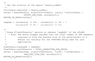
Here I printf the above  code for debugging. so regarding this below outputs. Would like to confirm with TI if the results is expected.

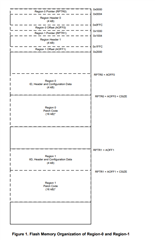
1. outdata array outputs for the active region and inactive region. so here is reg_addr is 0x70  (after bit shift).  and 0x20. 

2. the numof4ksector=0 , I assume the results should be 0x1000 (4096 in dec). 
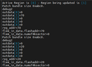
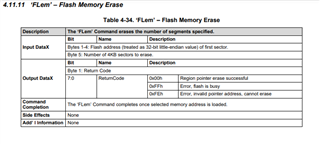
3. 

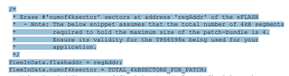
flemInData.numof4ksector = TOTAL_4kBSECTORS_FOR_PATCH;

About the MACRO #define TOTAL_4kBSECTORS_FOR_PATCH   is it  0x1000 ?

Thanks,
Sofian

  • Hi Sofian,

    We're looking into this and will provide feedback early next week, thank you for your patience! 

    Thanks and Regards,

    Raymond Lin

  • Hi Raymond,

    1. is there a way to just read one register from the TPS65988 spi flash? is it using FLrd ?

    2. I execute the flem on region 1, it seems that region 0 also being erased. 

    3. Do you have a chance to provide the previous feedback ?

    4. Which register that we could check the status of USB-PD provide the voltage limit ?

    Thanks,
    Sofian

  • Hi Sofian,

    Apologies for the delays, Raymond recently transferred teams. I will be taking over the case and will align with him to see where the resolution is currently at.

    1. is there a way to just read one register from the TPS65988 spi flash? is it using FLrd ?

    I may not be understanding this correctly, but the SPI flash is not formatted into registers. FLrd does allow you to read 16 bytes of the Flash starting at a specific bit in the Flash that you are interested in.

    For example, if you wanted to read some information at region header 0, you could use the FLrd command to and pass the flash address as 0x0004.

    2. I execute the flem on region 1, it seems that region 0 also being erased. 

    How are you determining that region 0 is being erased?

    The memory address that is erased is determined in the Input DataX field so you should check those input values and make sure they do not overlap with region 0.

    3. Do you have a chance to provide the previous feedback ?

    I am not the most familiar with this functionality and will see where raymond was at with this.

    4. Which register that we could check the status of USB-PD provide the voltage limit ?

    Thanks and Regards,

    Chris

  • Hi Sofian,

    In regards to your original questions about the App Note.

    The code is primarily for reference, and the original engineer is no longer with the team. In general, we recommend following the flowchart provided.

    About the MACRO #define TOTAL_4kBSECTORS_FOR_PATCH   is it  0x1000 ?

    I took a look at the code, and from my understanding, "flemInData.numof4ksector" indicates the number of 4kB segments required to hold the patch bundle. The comment you referenced gives an example of a max of "4", which would be 0x4 or 0b100. A value of 0x1000 would indicate 4096 4kB segments, which seems to be way too many. As the comment says, the patch size depends on your application and how large the patch you are adding. 

    Thanks and Regards,

    Chris

  • Hi Chris,

    1. Follow up the previous question and your answer, is there a way to just read one register from the TPS65988 spi flash? is it using FLrd ?

        » I have tried to access SPI Flash Address (0x0004) here the debug print out, what I read is the outdata[1]=0x20 , 

    flrd_data[0]=0
    flrd_data[1]=0
    flrd_data[2]=0
    flrd_data[3]=40
    FLRD cmd
    outdata[0]=0
    outdata[1]=20
    outdata[2]=0
    outdata[3]=0
    outdata[4]=0

        » Before I use the FLrd to access, I set the inacitve region (REGION 1) using FLrr to load the address of the flash memory for the selected region into the Output DataX.

    flrr_data[0]=1
    FLRR cmd
    outdata[0]=0
    outdata[1]=70
    outdata[2]=0
    outdata[3]=0
    outdata[4]=0
    outdata[5]=0

        » I tried to access the SPI Flash address (0x0004) and region 0x70 , here below print out outdata is FFFFFF.

    flrd_data[0]=4
    flrd_data[1]=0
    flrd_data[2]=0
    flrd_data[3]=70
    FLRD cmd
    outdata[0]=3
    outdata[1]=ff
    outdata[2]=ff
    outdata[3]=ff
    outdata[4]=0
    ..

    » then I tried to access the SPI Flash address (0x0004)  here below print out outdata is 0x20

    flrd_data[0]=0
    flrd_data[1]=0
    flrd_data[2]=0
    flrd_data[3]=40
    FLRD cmd
    outdata[0]=0
    outdata[1]=20
    outdata[2]=0
    outdata[3]=0
    outdata[4]=0
    ...

    2. Follow up the previous question and your answer, I execute the flem on region 1, it seems that region 0 also being erased. 

    flem_data[0]=0
    flem_data[1]=0
    flem_data[2]=0
    flem_data[3]=70

    flem_data[4]=c
    FLEM cmd
    outdata[0]=0
    outdata[1]=0
    outdata[2]=0
    outdata[3]=70
    outdata[4]=0

    I attached the total phase beagle transaction usb-pd-4cc-flem-data.csv

    I thought I only erased the region 1 ( inactive one) but somehow after the Reset GAID, the FW version look not correct.

    before I execute the FLem the version is f707.10.10, then after that reset become f707.10.00. 

    3. About your response regarding #define TOTAL_4kBSECTORS_FOR_PATCH 

        my patch files size is 43968 , so this below I calculated as 12 of total 4kB sectors for Patch. 

        43968/1024 = 43 (42.9) + 4 kB = 47 /4kB= 12 (11.75) 4kB Sectors

     4. Which register that we could check the status of USB-PD provide the voltage limit ?

          I checked my current value of the VBUS_OvpTripPoint = 0x26 (38)

          38 * 0.32  V + 3.84 V = 16 V  for USB 3.0  PD max. 5A @ 16V = 80 W. 

          We want to limit the VBUS to 27W. Is Software could do this changes? as TPS65988 could provide VBUS to 100 W

    Thanks,
    Sofian

  • Hi Sofian,

    1. Follow up the previous question and your answer, is there a way to just read one register from the TPS65988 spi flash? is it using FLrd ?

    The only way to read the flash using the TPS65988 is through the 'FLrd' Command. The command does not have an input to select the amount of data you are reading which means you are limited to the 16 Byte Output DataX read. When reading from the flash, we are not reading "registers". We are choosing a bit address and reading from that bit.

    2. Follow up the previous question and your answer, I execute the flem on region 1, it seems that region 0 also being erased. 

    From my understanding, the formatting of the flash can change and when choosing the number of 4KB sectors to erase, you need to be sure it will not overlap with other regions. This could happen if you choose too many regions. If your flash is formatted like the figure below, you may be erasing from the wrong start address. 

    3. About your response regarding #define TOTAL_4kBSECTORS_FOR_PATCH 

        my patch files size is 43968 , so this below I calculated as 12 of total 4kB sectors for Patch. 

        43968/1024 = 43 (42.9) + 4 kB = 47 /4kB= 12 (11.75) 4kB Sectors

    I would recommend trying this with your setup to verify it works, but this looks correct.

    Which register that we could check the status of USB-PD provide the voltage limit ?

    The voltage limit is set in the Port Configuration register 0x28.

    Thanks and Regards,

    Chris