


I am working on a power supply circuit, and am using a TPS61220 as one of the powering methods. Now the fact that its only one section of the power supply is less important, because even the fabricated test boards that have been made with just the charge pump have the same behavior. We are looking for it to take a single AA battery, and have the supplied voltage of 5.5V, with a nominal load current of approximately 1mA. The layout being used is the one from the "design considerations" section on page 15 of the datasheet.
The first thing that we noticed: When the battery is initially connected (about 70% of the time) the current consumption from the battery is 80mA - 100mA, the output voltage is around 2V. Since the current supplied to the load is only around 700uA under these conditions (confirmed with ammeter), I can only assume that most of that current is being shunted straight to ground somehow.
Once it has been pulled OUT of this first failure mode, (which takes a variety of odd steps, not always the same ones) and it starts operating "normally" (meaning only consuming about 5mA-7mA of current) it still only provides around 3.6V, and ballpark of 800uA to the load. Since this is an order of magnitude lower than its rated maximum current, it seems like it should be allot closer to 5.5V
The design uses a 4.7uH inductor although a 10uH has been tried also. The capacitors are each 10uF, and the feedback resistors are 1M and 100k.
It can be noted that unloaded, it does provide the correct voltage, but when a pot is added to simulate a resistive load, voltage drops precipitously with just a few hundred uA of load current.
Is this something anyone has seen before, or knows where one might start troubleshooting this problem? This is not an isolated incident, every one of the demonstration boards that has been made up has had the same problems. And the components have been changed quite radically just to see if it would make any difference (100uH inductor for example to see if it was the switching frequency that was somehow limiting the output power, it wouldn't even turn on with this size inductor, but it was worth a shot).
Is this the wrong component for this design? The datasheet seems to indicate that this is the ideal choice.
thank you in advance for your time


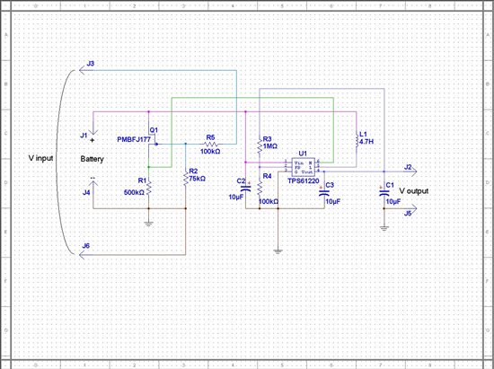 here is the schematic of the circuit.
 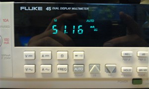 This is the output of the Fluke 45 during failure, and
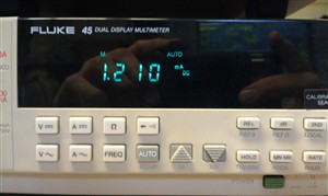 is when through adjusting the load and taking the battery in and out of the circuit repeatedly it finally entered a stable operating mode. The 1.2mA seems quite high, as there is no load between J2 and J5, but working better than 51mA.
 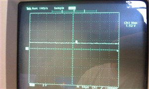 The EN input
 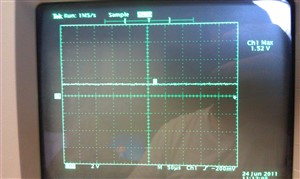 and Vin
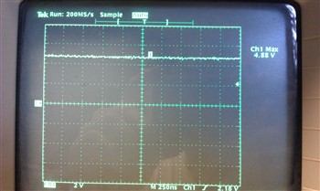 What is interesting, that by connecting a 10k trimpot between J2 and J5, when its at its maximum value, this is how Vout looks
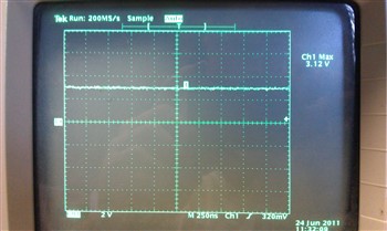 The output voltage immediately drops to 3.12V. Since this is only 312uA of current delivered to this load, that seems like a shockingly low value to drag Vout down so far.
 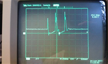 and this is what the inductor L pin output looks like. I suspect this may be the heart of the problem, as I was expecting this to be a far more continuous signal, not nearly as periodic as its appearing, but it seems to always do this unless its in its high current failure mode.
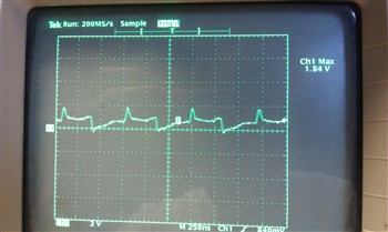 this is the L pin during the high current failure mode. Obviously something is wrong, but I threw it in for illustration of my suspicion that the normal operation of the L pin should be far more periodic.