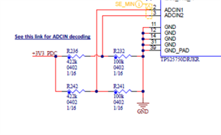
I have my circuit configured as indicated in the related question here: https://e2e.ti.com/support/power-management-group/power-management/f/power-management-forum/1130178/tps25750-charger-negotiation-voltage/4202856?tisearch=e2e-sitesearch. The only difference is I've configured ADCINx for AlwaysEnableSink.
There are situations when the dead battery flag is asserted and MODE=PTCH, but I am unable to load a patch or clear the dead battery flag.
Here's a register dump of the state I'm in, I highlighted the register fields of interest.
0x03 (MODE): [0x50 0x54 0x43 0x48]
0x50 ('P')
0x54 ('T')
0x43 ('C')
0x48 ('H')
0x14 (INT_EVENT1): [0x00 0x00 0x00 0x00 0x00 0x00 0x00 0x00 0x00 0x00 0x02]
PlugEarlyNotification: 0x0
ErrorPowerEventOccurred: 0x0
NewContractAsCons: 0x0
UsbHostPresent: 0x0
PatchLoaded: 0x0
ErrorCanProvideVoltageOrCurrentLater: 0x0
ErrorUnableToSource: 0x0
PDHardReset: 0x0
PPswitchingChanges: 0x0
NewContractAsProv: 0x0
PDStatusUpdate: 0x0
PRSwapComplete: 0x0
PlugInsertOrRemoval: 0x0
CMDComplete: 0x0
PowerStatusUpdate: 0x0
DRSwapComplete: 0x0
PRSwapRequested: 0x0
UsbHostPresentNoLonger: 0x0
ReadyForPatch: 0x1
ErrorMissingGetCapMessage: 0x0
I2CMasterNACKed: 0x0
TxMemBufferEmpty: 0x0
SourceCapMsgRcvd: 0x0
ErrorMessageData: 0x0
ErrorProtocolError: 0x0
ErrorDeviceIncompatible: 0x0
DRSwapRequested: 0x0
ErrorCannotProvideVoltageOrCurrent: 0x0
SnkTransitionComplete: 0x0
StatusUpdate: 0x0
0x2D (BOOT_STATUS): [0x34 0x03 0x62 0x02 0xA1]
PatchheaderErr: 0x0
DeadBatteryFlag: 0x1
PatchConfigSource: 0x0
MasterTSD: 0x0
patchdownloaderr: 0x0
I2cEepromPresent: 0x0
REV_ID: 0xA1
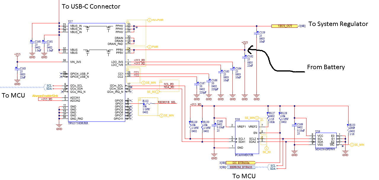
I'm not sure why the I2cEepromPresent is set to 0, since it is powered from LDO_3V3 which is regulated from VBUS_IN. But oh well here we are.
So when I try to execute the DBfg task, I get a "Task Rejected" return code. The MODE, INT_EVENT1, and BOOT_STATUS register contents are the same.
When I try to load a patch, After I write PBMs to the CMD1 register, I read it back and get a 0x40 byte with a NAK. Not sure what's going on.
I have attached the .json file I've used to generate the low region and full binary (and this is what is loaded on the EEPROM). I also attached the logic analyzer captures from the DBfg and PBMs tasks so you can see the raw i2c transactions.
Any thoughts on how I can clear the dead battery flag?
Thank you!
/cfs-file/__key/communityserver-discussions-components-files/196/DBfg.csv.txt
/cfs-file/__key/communityserver-discussions-components-files/196/23010600.json.txt
/cfs-file/__key/communityserver-discussions-components-files/196/PBMs.csv.txt