Hi
I'm looking for DC-DC regulators to transform 12V to +5V and -5V, 200mA for both outputs. It could be using two same/different chips. The only requirement is to have good noise/ripple performance(<1%).
Thanks!
This thread has been locked.
If you have a related question, please click the "Ask a related question" button in the top right corner. The newly created question will be automatically linked to this question.
Hi
I'm looking for DC-DC regulators to transform 12V to +5V and -5V, 200mA for both outputs. It could be using two same/different chips. The only requirement is to have good noise/ripple performance(<1%).
Thanks!
Hello,
The TPS62913 Low Noise and Low Ripple DC/DC buck converter can be used in an inverting buckboost (IBB) configuration to provide -5V from 12V input. Evaluation modules are available for the buck evaluation and IBB evaluation:
Buck:https://www.ti.com/tool/TPS62913EVM-077
IBB: https://www.ti.com/tool/TPS62913-IBB-EVM
More information on the device is available on the product page here: https://www.ti.com/product/TPS62913
Please let me know if you have additional questions.
Hi Steve,
Thanks for your suggestion!
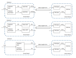
1)The original target of this design is to take place of the 12V to ±9 part in my circuit (See the scheme 1). But based on the TPS62913 you suggest I think I can go for scheme 3. But I'm not sure if scheme 2 is much safer to filter all the possible ripple on power board - or I'm just doing over-engineering things.
Load current is corrected to 1A/0.6A.
2)I have a cable around 0.4m between the power board and sensor board. What shall I keep in mind to reduce the ripple and noise(including EMI noise) as possible?
Looking forward to your reply:)

Hello,
The TPS62913 has an output voltage limit of 5.5V, so the +/-9V output is not possible with that device. It would be possible to do that without the LDO after it, and regulate directly to +/-5V. The TPS62913 has a feedback sense that can be placed close to the load, but I would avoid doing it 0.4m away. Please take a look at the noise and ripple performance of the TPS62913 and see if this will meet your needs without the LDOs.
Hello,
The 0.4m cable can be handled in a few different ways. If you know the inductance and resistance of the cable, including any connectors, then you can take that into consideration and determine what is the most important for your design:
1. Design your power supply to account for the load drop across the cable (i.e., set the output voltage slightly higher to achieve the desired DC voltage at the end of the cable under the expected load). This is the simplest, and can be done with a switcher or LDO. However, the DC regulation will be different for various loads.
2. Design the feedback to be at the end of the cable. Typically, this will require a device with a true differential remote sense, and is the most difficult to design for stability. However, you can achieve the highest efficiency.
3. Use a switcher for your initial step-down to a high enough votlage and then regulate with an LDO or switcher at the other end of the cable. This is the simplest with the best DC regulation, but requires more components and will have the lowest efficiency.