This thread has been locked.

If you have a related question, please click the "Ask a related question" button in the top right corner. The newly created question will be automatically linked to this question.

BQ40Z50-R2: How to setup shutdown feature with Vstartup and Charger present Threshold

Part Number: BQ40Z50-R2
Other Parts Discussed in Thread: BQ40Z50, EV2400, BQSTUDIO

Hello,

I use a 4 cell configuration. I want to protect of under voltage cell (CUV) by opening FET automatically. Then below 2.9V of a cell (11.6V of stack for worst case), I want that FET switch off. Charger will wakeup system for charging.

I do not understand how to configure register for shutdown feature with PACK pin and configuration of charger present threshold register

I attached 5 picture to explain :

1) the PACK pin is connected to power bus that come from cell stack. Then power bus is not reserved for charger, it is the main line for stack cell too, Voltage can be 11.6V to 16.8V for example in normal operation


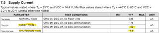
2) in state machine,

- switch from normal to shutdown is relative to "min cell voltage" and "charger presence treshold". These ones are registers, I find it in datasheet

- return from shutdown to normal is relative to "Vstartup", but I do not find any register

3) Conditions of switching mode are relative to PACK pin (see scheme upside), then I supposed to find registers that can be configured a few volts for 2,3 or 4 cells configuration (for me 4 cells)

4) the only "startup" word that I find in documentation is on HW datasheet and fixed to 2.25V. Then the 4 cell stack can never be under 2.25V (4 cells is about 8V..., lower is destructive). Then if it is the startup value used for switching mode, it always exit of shutdown because condition will be always true ! Then it is impossible (8V is > 2.25V !)

5) and for finish my mis-understood, the "charger present threshold" is set under 3V and it seems to have a contradiction

register seems to be cell-based and not stack-based

Then, I do not understand how to

- set vstartup for 4 cells

- set charger threshold for 4 cells

Thanks if you can help me.

Regards

  • Hello Cedric,

    I think there may be a couple misunderstandings with the terms and operation they imply.

    When the gauge is in shutdown mode both FETs are offer, this means the only voltage that should ever be applied to the PACK pin is from a charger, in which case the gauge should wakeup and begin operation again. Vstartup is not configurable and it shouldn't need to be adjusted since nothing should be on the system power bus in shutdown supplying voltage unless it's the charger.

     The charger present threshold is just to prevent the gauge from going to shutdown when there actually is a charger present, that's why it says if the charger supplies less than 3V then you should move it lower. Basically if the charger is present we should not go to shutdown mode. You can set the charger present threshold to just below the lowest voltage you expect from your charger, it shouldn't be a critical parameter for operation of the feature.

    Charger Present Threshold: Only used going into shutdown mode.

    Vstartup: Only used from exiting shutdown mode.

    Sincerely,

    Wyatt Keller

  • Hello,

    Thanks for quick reply.

    I understood your remarks, but I think there is a flaw in the analysis.
    The output of my BMU (so after the FETs) is loaded by a circuit that can be idle (few µAmps) with a capactive energy reserve.
    The consumption can therefore be very low and maintained by the capacitors for a long time.
    Thus, if the gauge goes into shutdown, the measured voltage Vpack does not drop to 2.25V, it can be maintained at 10V, 9V...8V and so on until death occurs.

    this is why the 2.25 or 3V setting cannot be used.

    Do you confirm that the operation you indicate is only possible if the output of the FETs drops to zero suddenly, so without residual voltage by capacitors?

    How can I do ?

    Regards

    C.M.

  • Hello Cedric,

    This is not the usual implementation of the gauge, generally when the gauge shuts off the FETs it is for protection so we would not want or expect voltage to be on the system side, unless there was a charger present. You would need to isolate the PACK+ and PACK- from any voltages that still remain on your system.

    Sincerely,

    Wyatt Keller

  • Hello again,

    I do not know if we can say that it is unusual because there is no contraindication to consuming little and having a capacitive load. There is no "voltage" on the system side, just a slow discharge.
    The problem is that thresholds may be usable with one cell, but not with 4 cells stack.
    The FETs are well used in protection, I see nothing abnormal in the use. It is operation at low thresholds, without any time delay, that poses a problem.
    How to configure the gauge so that it can work?
    The BMU is made, just like the cards plugged into it.
    I noticed the problem because the BMU had remained unused for a long time, and it ended up dying because it stops and restarts in a loop...

    Regards

  • Hello Cedric,

    I'm not sure I understand completely, if the gauge turns off the FETs and you have a capacitive load on the system side there would be a voltage on the PACK pin that will prevent the gauge from going to shutdown until the caps discharge from whatever leakage or small system load is present.

    There must be a voltage below the Vstartup on the pack pin, this is part of the hardware design so your system would need make sure there is no voltage on the PACK pin if you want to enter shutdown, most likely you will need some hardware to do this.

    Sincerely,

    Wyatt Keller

  • Hello,

    The "PACK" pin is connected as recommended in the application diagram, ie after the FETs.
    The "PACK" pin therefore sees the output voltage of the BMU, therefore the input voltage of my system. The load is, as I said, sufficiently capactive and consuming little for the residual voltage to persist for a while.
    Having an output load of this type is nothing special, it's classic. So I don't understand how it couldn't be possible to handle this configuration.

    As the BMU manages its protections, I don't see how my load could take into account a stoppage of the BMU, and system load would have to be able to commit suicide!
    The whole problem comes a priori from the "Vstartup" threshold which does not work with 4 cells stack (but only one cell), whereas the component is made to manage from one to four cells.

    What is the parade or the configuration to implement?

    Regards,

    CM

  • Hello Cedric,

    From my experience in battery management system implementing gauges this is not a usual application since I have not seen this type of issue appear before, I believe most of the time the system drains any capacitive voltage on the system side quick enough where it would not wakeup the gauge from shutdown and cause the issue you see where it oscillates in shutdown and normal mode. Or if the voltage does stay long enough they implement some type of pulldown to drain the voltage if the gauge says the system should be disabled.

    I did find one other thread with similar question, I believe they got it working as desired by using the EMSHUT feature: https://e2e.ti.com/support/power-management-group/power-management/f/power-management-forum/1013200/bq40z50-r1-charger-present-threshold-increased-but-device-still-waking-up-from-shutdown-with-voltage-applied-is-less-than-threshold

    Generally once the gauge turns the FETs off the system should be shutdown (unless there is a charger present to supply system voltage). The Vstartup threshold is set to work with all cell configurations. Unless there is a hardware protection there are safety alerts for almost all protections that can notify the host the the system will be shutdown soon and the host should use this time to do any cleanup before shutting down.

    Sincerely,

    Wyatt Keller

  • Admittedly, this is not usual, but it is still possible.

    This is not a problem as long as one does not approach a deep discharge and recharges regularly.
    The implementation of a pulldown would imply, as I said, a managed suicide management.

    I looked at the post you pointed me to. There are similarities but:
    - there it is an operation without reaching the deep discharge
    - as for me, it sees the unwanted wakeup because Vstartup is too low for 4x cell stack operation
    - it uses SMBUS commands from a master, in my case it is an autonomous operation (it is the BMU which manages itself to protect itself)
    - I can't deactivate the option because I need to be able to wake up with the charger

    The Vstartup threshold is NOT defined to work with all cell configurations because it is fixed at 2.25V and not at 4x2.25V for a stack as it should be.
    When the load is on standby, it no longer communicates, so I can't monitor the charging status or alerts.
    This threshold has Vstartup fixed at 2.25V is a real technical limitation which prevents operation with 2, 3 or 4 cells in series.

    I don't see how to solve this problem.

  • Hello Cedric,

    Most system we work with are prepared to lose power since they are battery operated they must be able to handle this condition. If the protection from the gauge is firmware then it allows the host to do the cleanup and shutdown before the FETs are turned off.

    I'm not sure how the deep discharge state affects the functionality for wakeup.

    The Vstartup had to be low enough for a single cell charger to wakeup the gauge, since it is a analog threshold this would require extra trim setting to configure, not just firmware change. It also works for multi-cell since the gauge disables the FETs so the stack voltage is not present on the PACK pin. The gauge functionality assumes the voltage on the PACK+/PACK- pins is zero when the protections are triggered since this is a safety event, regardless of cell count. The system doesn't need to be active for the gauge to wakeup and broadcast to the charger when the charger is inserted.

    The Vstartup threshold is not viewed as a technical limitation of the gauge since the PACK voltage should be 0V when protection FETs are triggered for all cell configs. You should only be able to communicate with the gauge when a protection is triggered that disables both FETs, not the entire system since there is normally a protective reason to prevent the system from being active.

    Sincerely,

    Wyatt Keller

  • Hello,
    I understood your remarks, but that is not the substantive issue.
    I have no problem with my system, ie I don't need to clean it or prepare for shutdown when the power source becomes too weak. When the power goes away, my system shuts down harmlessly.

    Here the problem is that the BMU never shuts down and therefore ends up destroying the cells (by full discharge) because it does not shut down because of the Vstartup threshold which is unsuitable for 4x cells stack.
    It is the BMU's protection function that does not play its role, that is to say that the FETs must open in the event of a low energy level of the cells.

    As you rightly say, the threshold is suitable for a single cell, but only for a single cell. However, as the gas gauge chip can be configured with 2, 3 or 4 cells, this fixed threshold becomes problematic.
    The operation you indicate at 0V is only possible in an ideal and perfect case. Here Vpack measures a residual voltage, but it would be necessary to be able to manage the threshold, the time of the filter or that the BMU pilots itself a discharge with a circuitry of evacuation of the capacitive voltages.

    Regarding your other remark, the system doesn't need to be active to wake up the gauge with the charger, and it is, so that's beside the point.
    Again, cell protection should have the effect of opening the FETs, and that's exactly what doesn't work since the Vstartup threshold is fixed for a single cell and not 4x cells stack, so the FETs stay on.

    The Vstartup threshold is therefore a technical limitation.

    I therefore renew my question: what parade can I implement on the BMU side (gauge) to overcome this problem?

    Regards,

    CM

  • Hello Cedric,

    The only firmware work around would be implementing a longer delay between when the FETs turn off before shutdown to give your system more time to drain the capacitance on the load. If the 254s max is not long enough you would need to add hardware in order to pulldown the pack pin.

    The delay I'm refering to is in the TRM section 15.5.4.2 Delay.

    Sincerely,

    Wyatt Keller

  • Hello,
    Thank you for this quick feedback.

    I looked at the "ship" section (§15) that you pointed out to me. There is no detailed explanation of these parameters (as in section §5 which does not detail), it is quite obscure, do you have additional documentation (eg diagrams, application note...) .

    "Ship" reminds me of IATA usage, but a priori not only.
    The setting seems to be implied by at least two parameters "FET OFF time" and "delay", and while searching the internet for these keywords I found another post you replied to 2 years ago:

    https://e2e. ti.com/support/power-management-group/power-management/f/power-management-forum/930567/bq40z50-r1-bq40z50-r1-shutdown-time-ship-delay-suv-delay-parameter-configuration- issues

    Other parameters were affected.

    On the other hand, the question of the capacitive load was already a problem, so my problem is not a priori new as mentioned at the very beginning of the post.

    1) For your second proposal to disconnect the Vpack pin, is there a way to do it by the gauge?

    2) So, do you have more information about how "ship" works?
    I want the protection to be usable anytime during the life of the product, not just at initialization or during the shipping phase.

    Regards,

    C.M

  • Hello Cedric,

    Another important thing we should verify is what method you are entering shutdown from? Since there are multiple pathways to enter shutdown (time, voltage, power save, cmd)

    The ship mode is the same as shutdown mode, the main difference is which method used to enter the mode.

    The new firmware releases of the BQ40Z50 (R3 and R4) you can use some of the pins as GPIOs and map it to a bit in the gauge, you could link it to the SDM bit and pull the PACK pin low. Or have some hardware that could be enabled when the FETs are turned off to drain the PACK side with a pull-down.

    Sincerely,

    Wyatt Keller

  • Hello,

    I had been waiting for your answer for some time and it was starting to worry me (because I have already problem and I must solve it).
    I was going to get back to you, and it's surprising because your answer is dated for almost 30 days while it's still a few days ago, there was no answer (several checks), and I did not receive any notifications (like all others posts).
    In addition, the login page to answer was blocked (read only, and login do not unlock), I had to go through the parent site account to access it by child clic. I supposed there is a mismake since several week on website.
    So sorry.

    For the points covered:
    1) The use of GPIO of the gauge to drive a circuitry to drain Vpack interests me if the operation is 100% complete and autonomous, without external control.
    i.e. the GPIO can operate when stopped, but also on restarting when the charger voltage returns.
    According to the doc, "OperationStatusB" bit 0 is SDM, so the bit is the FET shutdown image. I will use LEDCNTLA, then register Flag Map set up 1 will be:
       --> 0xB303  (Enable, HiZ/GND inverted, OR, LEDCNTL1, bit 0, OperationStatusB)
    The return state of the SDM bit to 0 is not clearly defined (no info on its state after the time-out)
    As the wake-up is done by the PACK pin, rather than disconnecting PACK by a transistor for example, the GPIO would therefore rather be used to add a pulldown to PACK in synchronism with the stopping of the FETs (via resistor between PACK and LEDCNTLA).
    We then have 2 scenarios depending on the behavior of SDM
    - If SDM remains at 1, the pulldown remains,
    - if SDM returns to 0 at the end of the shutdown timeout, the pulldown is disconnected, but that would not matter because the system would be unloaded.
    When the load is detected, SDM returns to 0 if it was not already done and the pulldown would be disconnected.

    Am I right ?

    I will use the -R3 version to benefit from this setting

    2) I still don't have more information about the "ship" mode.
    I can't find any clear information on how it works

    For your remark about the stop entry mode, I enter stop mode only by the internal strategy of the gauge.
    I don't have any external controls, so that's why it just depends on the inner workings of the gauge.

    Regards,

    Cédric Milleret

  • Hello Cédric,

    The GPIO config should be explained in the TRM, I believe there are also some examples given. Depending on how you enter shutdown mode SDV/SDM bits could be used. For some of the shutdown mode entries there is no bit. But those are the time based and at that point I would assume the system voltage should be low enough.

    I would use the most recent firmware if possible since it has the most features and fixes, R5 was just released.

    There is no information on ship mode, ship mode is the same as shutdown mode. Instead of a low power or other method to enter shutdown, ship mode commands are used to place the gauge into shutdown. They are the same state for the gauge.

    Sincerely,

    Wyatt Keller

  • Hello,
    Thanks for your quick reply.
    Yes, I have just studied the documentation (compared to your previous answer) and that is why I explained to you what I intended to do and I wanted your confirmation, because I did not find any application note about of this pulldown discharge method directly via the GPIO pin controlled by an internal bit.
    I have to be sure that the SDM bit is suitable for ALL cases of stopping, but a priori here it would rather be the SDV bit which corresponds the most to my case.
    Looking for the shutdown modes, I count 3 of them, there is also EMSHUT.
    It would therefore be necessary to "OR" the 3 conditions on the same pin, because it seems to be possible and more usuable to put the 3 pins in parallel (in OD HiZ) with each a condition.
    The goal is ultimate protection, therefore SDV because it is the cell voltage that counts.

    I have noted your remark about the -R5 revision.
    I will look closely to make the migration at the same time as this evolution, but a priori by browsing the docs, I do not see any difference as to SDM/SDV/EMSHUT. Then I can test it on -R3 first

    It is noted for the "ship" mode. So No difference except direct access by command.

    Then, do you confimed :
    - the pulldown wired on LEDCNTLA (like 1kohm because limited to internal current generator at 22.5mA, and max stack voltage of 4 cells), and other end to PACK pin
    - FlagMapSetUpX = 0xB3xx (X to be 1,2,3 ; xx to be OperationStatus and bit below)
    - "OR" condition of OperationStatusB bit 0, OperationStatusA bit 10, OperationStatusA bit 6
    - voltage returns (by charger) remove condition, and LEDCNTLA goes HiZ

    Regards,
    CM

  • Hello Cedric,

    We do not have any documentation on this type of work around, as mentioned during the beginning of the thread this is an uncommon issue.

    I think you may be able to get something working with the GPIO functionality of the pins, but I have not tested it so you may need to do some verification if it will work with your system.

    Sincerely,

    Wyatt Keller

  • Hello,

    I prototyped a test today with a GPIO configured with SDV. I reduce Vpack gradually with a laboratory supply, I check SDV bit in BqStudio with EV2400.

    I see SDV change in BqStudio.

    Unfortunately I ran into a problem that I visualized with the scope, the GPIO pin becomes Hi-Z at shutdown, but it is precisely at this transition that the SDV bit is activated, so the pin never changes state because it is at this time in Hi-Z.
    It is therefore confirmed the doc (-R3 and -R5), GPIO chapter

    So, is there a way to delay GPIO Hi-Z shutdown ?

    Regards,

    CM

  • Hello Cedric,

    The only way to control the GPIOs is by the flags, those are the only flags that I'm aware that would give some indication, unless you configured a different feature to try to estimate when shutdown mode will enter, like BTP_INT but I don't know if this will have the desired functionality.

    Sincerely,

    Wyatt Keller

  • Hello,

    The principle of the GPIOs seems to correspond but I come up against a new limitation at each stage.
    Shutdown modes have probably never been anticipated and tested, especially for a 4-cell design.
    I'm surprised to be the only one concerned.

    Here, it is the shutdown phase which deactivates the GPIOs when we would like to use the shutdown bits, so the flags are available but not usable.

    In the -rev1 version of the chip, the GPIOs did not exist, then the functionality appeared from -rev2.
    Are the GPIOs put in hi-Z by FW or by HW?
    I have the impression that it is FW because the GPIO_PF bit allows to control LEDCNTLC in case of PF only for the case of FUSE, and the output does not go to Hi-Z

    I have no other external means of controlling the shutdown, and moreover to benefit from ultra-low-power electronics like the gauge does, it is necessary to use only the gauge.

    For BTP_INT, it's not synchronous with the FET shutdown but based on the SOC, so it's not at all equivalent to IO with flags.

    Regards,

    CM

  • Hello Cedric,

    We have not tested every configuration of the GPIO mapping since some of the bits (like you have found) may not be able to function correctly with the mapping for them.

    The pins have always had GPIO functionality, the FW did not support the configuration options in the older firmware releases. I think keeping the gauge in sleep instead of shutdown (besides maybe before shipment) would be the best solution even though it is not ideal.

    I did not think the BTP_INT would match exactly but wanted to mention in case it could, I do not know all the details of your application.

    Sincerely,

    Wyatt Keller

  • Hello,

    That's a real problem. GPIO can't be used in this state. Is GPIO hi-Z state controlled by HW shutdown or FW shutdown strategy ?

    Sleep mode is not equivalent of shutdown mode, consumption is very higher, and it is not conform with my design.

    I was already blocked on this subject.

    Regards,

    CM

  • Hello Cedric,

    The GPIOs are set to hi-z mode when the gauge is in shutdown. All of the control before shutdown is within firmware. Firmware initiates the shutdown sequence. It is not possible to control GPIOs since all internal circuitry is off in shutdown.

    Sincerely,

    Wyatt Keller

  • Hello,

    OK, then it is FW that control shutdown and puts GPIO to Hi-Z.

    Then a FW update would be a way :

    - to delay GPIO Hi-Z when shutdown occurs (SDV, SDM, EMSHUT) with for example by a delay register

    - to not Hi-Z GPIO that concern by SDV, SDM, EMSHUT, if current of Vol logic is null (because there is current source inside)

    Regards

    CM

  • Hello Cedric,

    A FW change would be needed in order to get the exact behavior needed. Or additional hardware/system change to prevent voltage from always being on the PACK pin even when trying to shutdown.

    Sincerely,

    Wyatt Keller

  • Hello,

    We agree on these points.

    What do you suggest in this case?

    Regards,

    CM

  • Hello Cedric,

    I'm not sure if there is a workaround that does not involve some level of hardware change.

    Sincerely,

    Wyatt Keller

  • Hello,

    OK, I want to do something, but I need a source of control signal. I can make external circuitery to fast discharge VPACK

    Only the gauge can triggering event. So I need a GPIO that can control external circuit.

    You tell previously about a FW change, what can you consider?

    Regards

    CM

  • Hello Cedric,

    We are not able to make custom FW for all customers, the only thing I could do is put in a request for the SDV/SDM bit to give some extra time for GPIO mapping to discharge the PACK. This has no set timeline yet and will most likely not be for many months.

    Sincerely,

    Wyatt Keller

  • Hello,

    Today I am dependent on a defect of the chip which is designed for 4 cells in series but which only works with one with regard to the shutdown.
    This chip was also recommended to me by TI support after another fault of another version (z60) which could not be solved, so I had to redesign my system.
    This puts me in a very complicated situation because I don't know how to solve this problem, it's a dead end again.
    It's not the first setback I've had with TI gauges where problems persist, and I'm the one who pays the consequences, knowing that with the shortage, I didn't even have priority, and I paid 10x the price for the components to have them.
    So now what do I do?

    Regards,

    CM

  • Hello Cedric,

    The function is not a defect of the chip, the functionality is described in the TRM and datasheet. I believe there may still be some misunderstanding on how this is intended to be implemented.

    I know this was mentioned near the beginning of the post but I don't recall if it was tested, I just did some testing myself with our EVM. I set Charger Present Voltage at approximately Vstartup, the gauge stays in the condition where XDSG is set and SDV is set until the other conditions are met (voltage()<charger present) Are you able to set the charger voltage threshold to the Vstartup threshold so it doesn't toggle between modes when the shutdown starts?

    If your caps are very large and slow discharge I think it still may loop but I think it is worth a try. Also the GPIOs are set to hi-z when SDV is set, I was able to see this on my bench. But they still do respond momentarily to the manual GPIOwrite() command. If your host is still active from the caps then you could send this command to pull-down the voltage until the host turns off.

    Sincerely,

    Wyatt Keller

  • Hello,

    The chip is supposed to work for 1 to 4 cells, but the shutdown only works for one cell, so it's a defect.
    Setting the charger voltage to Vstartup is of no interest since the pack voltage is 4x Vstartup at the minimum, and opening the FETs does not allow the voltage to drop with the capacitors, Vpack still seeing the voltage of 4x Vstartup.
    All these tests have already been attempted.
    My host is sleep when this adverse event occurs, so it does not monitor the system and cannot send commands.
    Admitting that this is possible, it would be necessary to place the FETs in shutdown before driving a discharge circuitry, to force the shutdown, but the GPIOs would then no longer be usable because in Hi-Z, so we are going around in circles with this problem because it must synchronize the pins and they remain active, and the gauge does not allow it.
    This solution imposes a host, so it means that the gauge does not manage the shutdown itself while it is a basic function.
    The discharge circuit is dependent on the state of the FETs, but they are controlled by the gauge, so this would imply a double control by the host, by re-use parameters (no duplicate) of gauge by reading memory and do some algorithm.

    Regards,

    CM

  • Hello Cedric,

    Let me double check with our systems engineer if there are any work arounds for this, I should hear back from him within the next couple days.

    I'm not sure if there is a good solution for your system, our gauge is mainly designed for applications which only have system voltage when a charger is present or the FETs are on. This configuration has been used by hundreds of different customers and designs for multicell packs.

    Sincerely,

    Wyatt Keller

  • Hello Cedric,

    This was the systems team response and advice:

    The voltages are pretty flexible but the timing for the voltage based shutdown only has 255 seconds as the max so this may be the limit.

    One other option is to use the Auto Ship Time to get a timer in minutes. We could turn the FETs OFF, go to sleep and then after x mins go to SHUTDOWN. The only issue with this is that if the voltage doesn’t fall low enough then the device won’t go to SHUTDOWN.

    Do you know how long it takes for the voltage on the PACK pin to fall below the Vstartup?

    Sincerely,

    Wyatt Keller

  • Hello,

    Last week I tried several hardware techniques to cut-off the voltage of VPACK during the shutdown phase, because contrary to what the system technical support claims, the voltages are not pretty flexible since Vstartup is fixed in hardware to a unique value, regardless of the number of cells.

    In my use, it is normal that the gauge can be in sleep for a very long time, so if I use auto ship, the gauge could go into shutdown when it is only a very long standby, so this does not is not possible because my system would then be switched off.

    I am doing a test campaign to see the possible cases because there are a number of scenarios depending on the current consumed, the state of charge...

    I've had a few setbacks before as there is always a special case that compromises proper detection.

    Regards

    CM

  • Hello Cedric,

    The system engineer was referencing the shutdown voltage I believe, which is configurable in the firmware. The startup voltage is fixed in the hardware as you mention.

    I'm sorry there is not an easier solution, when I discussed with out systems engineer he has also not come across this type of issue before, usually the time range we provide in firmware between FETs off and actual shutdown is long enough to prevent this behavior.

    Sincerely,

    Wyatt Keller