Other Parts Discussed in Thread: LM317
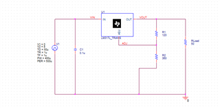
I have tried using the LM317L_TRANS spice model in LTSPICE
** Released by: WEBENCH Design Center, Texas Instruments Inc.
* Part: LM317L
* Date: 02SEP2016
* Model Type: Transient
* Simulator: PSPICE
* Simulator Version: 16.2.0.p001
But it does not work
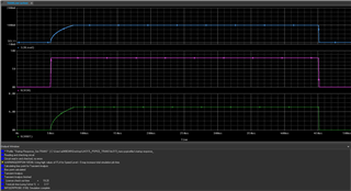
The output voltage waveform stops at 0us 400pV.
if I use the LM317 model (high current) it works fine
Please provide any suggestions
Thank you
Fausto Bartra
The spice file below
*$
* LM317L
*****************************************************************************
* (C) Copyright 2016 Texas Instruments Incorporated. All rights reserved.
*****************************************************************************
** This model is designed as an aid for customers of Texas Instruments.
** TI and its licensors and suppliers make no warranties, either expressed
** or implied, with respect to this model, including the warranties of
** merchantability or fitness for a particular purpose. The model is
** provided solely on an "as is" basis. The entire risk as to its quality
** and performance is with the customer.
*****************************************************************************
*
** Released by: WEBENCH Design Center, Texas Instruments Inc.
* Part: LM317L
* Date: 02SEP2016
* Model Type: Transient
* Simulator: PSPICE
* Simulator Version: 16.2.0.p001
* EVM Order Number: NA
* EVM User's Guide: NA
* Datasheet: SLCS144E–JULY 2004–REVISED OCTOBER 2014
*
* Model Version: Final 1.00
*
*****************************************************************************
*
* Updates:
*
* Final 1.00
* Release to Web
*
*****************************************************************************
*
* Model Usage Notes:
*
* A. Features have been modelled
* 1. Startup & Shutdown Response
* 2. 200mA Peak Current Limit
* 3. Dropout Voltage vs Output Current
* 4. Line & Load Transient Response
* 5. VOUT vs VIN Plot
* 6. VOUT vs IOUT Plot
*
* B. Features haven't been modelled
* 1. ADJUSTMENT pin Current
* 2. Ripple Regulation & Output Noise Voltage
* 3. Temperature dependent characteristics
*
*****************************************************************************
.SUBCKT LM317L_TRANS IN ADJ OUT
X_F1 VZZ N16902334 N16902368 VYY LM317L_F1
C_C3 VYY 0 100p
X_S1 N16902539 0 IN N16902368 LM317L_S1
R_R5 VZZ VYY {ROUT}
E_ABM2 N16902633 0 VALUE { IF(V(IN_OK) > 0.5, 1, 0) }
X_S2 IN_OK 0 N16902267 OUT LM317L_S2
C_C5 N16902539 0 1n
R_R7 N16902539 N16902633 100 TC=0,0
X_U5 N16902428 VYY N16902393 0 RVAR PARAMS: RREF=1
E_E1 N16902393 0 TABLE { V(ISENSE, 0) }
+ ( (2.5m,1.2) (100m,15)(150m,15) )
R_U1_R2 0 U1_N15555780 1G
E_U1_ABM4 U1_N15555938 0 VALUE {
+ V(U1_N15543421)*(ABS(V(OUT))/(ABS(V(OUT)-V(ADJ)))) }
E_U1_ABM6 U1_N15543747 0 VALUE { IF(V(IN_OK) > 0.5, V(U1_N15543395), 0)
+ }
R_U1_R1 0 U1_N15543421 1G
E_U1_E1 U1_VDO 0 TABLE { V(U1_N15543843)-V(0) }
+ ((0,1)(2.25m,1.5)(10m,1.66)(20m,1.72)(30m,1.76)(40m,1.78)(50m,1.82)(60m,1.85)
+(70m,1.88)(80m,1.92)(90m,1.97)(100m,2))
V_U1_V1 U1_N15543395 0 1.25
V_U1_V5 U1_N15543883 0 1.01
R_U1_R5 U1_N15543687 N16902490 1 TC=0,0
X_U1_U7 IN U1_N15543883 IN_OK COMP_BASIC_GEN PARAMS: VDD=1 VSS=0
+ VTHRESH=0.5
C_U1_C3 N16902490 0 10p
E_U1_ABM5 U1_N15543687 0 VALUE { MIN(V(U1_N15555780),
+ MAX(V(IN) - V(U1_VDO), 0)) }
C_U1_C2 U1_N15555780 0 10p
C_U1_C1 U1_N15543421 0 {1e-6*SQRT(TTRN)}
R_U1_R4 U1_N15555938 U1_N15555780 1 TC=0,0
E_U1_ABM7 U1_N15543843 0 VALUE { LIMIT(V(ISENSE)- 2.262m, 0, 100m)}
R_U1_R3 U1_N15543747 U1_N15543421 {3.333e5*SQRT(TTRN)} TC=0,0
E_ABM1 N16902428 0 VALUE { MIN(V(VXX), (V(Vzz)+(ILIM*ROUT))) }
X_U2 0 OUT d_d
R_R2 N16902490 VXX {PSRR*RINP}
C_C1 VXX N16902368 {1/(6.28*RINP*POLE)}
C_C2 N16902490 VXX {1/(6.28*PSRR*RINP*ZERO)}
X_H1 N16902334 N16902267 ISENSE 0 LM317L_H1
R_R1 N16902368 VXX {RINP}
.PARAM PSRR=1.778e-3 ILIM=200m POLE=6k RINP=10e6 ZERO=800k ROUT=1m
+TTRN=1u VREF=1.25
.ENDS LM317L_TRANS
*$
.SUBCKT LM317L_F1 1 2 3 4
F_F1 3 4 VF_F1 1
VF_F1 1 2 0V
.ENDS LM317L_F1
*$
.SUBCKT LM317L_S1 1 2 3 4
S_S1 3 4 1 2 _S1
RS_S1 1 2 1G
.MODEL _S1 VSWITCH Roff=100 Ron=50 Voff=0.2 Von=0.8
.ENDS LM317L_S1
*$
.SUBCKT LM317L_S2 1 2 3 4
S_S2 3 4 1 2 _S2
RS_S2 1 2 1G
.MODEL _S2 VSWITCH Roff=100E6 Ron=1m Voff=0.2 Von=0.8
.ENDS LM317L_S2
*$
.SUBCKT LM317L_H1 1 2 3 4
H_H1 3 4 VH_H1 1
VH_H1 1 2 0V
.ENDS LM317L_H1
***************************** Basic Components *****************************
*$
.SUBCKT COMP_BASIC_GEN INP INM Y PARAMS: VDD=1 VSS=0 VTHRESH=0.5
E_ABM Yint 0 VALUE {IF (V(INP) >
+ V(INM), {VDD},{VSS})}
R1 Yint Y 1
C1 Y 0 1n
.ENDS COMP_BASIC_GEN
*$
.SUBCKT D_D 1 2
D1 1 2 DD1
.MODEL dd1 d (Is = 1E-15 N = 0.1 TT = 10p)
.ENDS D_D
*$
.SUBCKT RVAR 101 102 201 202 PARAMS: RREF=1
* nodes : 101 102 : nodes between which variable resistance is placed
* 201 202 : nodes to whose voltage the resistance is proportional
* parameters : rref : reference value of the resistance
rin 201 202 1G; input resistance
r 301 0 {rref}
fcopy 0 301 vsense 1; copy output current thru Z
eout 101 106 poly(2) 201 202 301 0 0 0 0 0 1; multiply VoverZ with Vctrl
vsense 106 102 0; sense iout
.ENDS RVAR
*$
.SUBCKT D_D1 1 2
D1 1 2 DD1
.MODEL DD1 D (IS = 1E-15 N = 0.1 TT = 10p)
.ENDS D_D1
*$


