This thread has been locked.

If you have a related question, please click the "Ask a related question" button in the top right corner. The newly created question will be automatically linked to this question.

BQ76940: Cells in Cell Group 2 discharged to 0V. AFE reported cell connection error.

Part Number: BQ76940
Other Parts Discussed in Thread: STRIKE

We've been using BQ694003 in our BMS for quite a while now and we recently faced a very strange issue with a 14S13P pack.

All the cells in cell group 2 (C6 to C10) are at 0V. When we checked the logs, we saw the AFE reporting cell connection error. All the other cells are at 3.7V and are working fine without any problems. 

The questions we have are, 1, how did those cells go down to 0V? The AFE should cut off the discharge right? Did it discharge through the balancing circuit? 

2, Apart from the possibility of a physical disconnection of the cell connector, can any other passive component failure cause the AFE to report a cell connection error? For ex, maybe the reference for cell group 2 was lost or CAP2 failed?

  • Hello Abhijith,

    Are the cells all 0-V? Or is this the value being measured by the IC? What is the exact protection that is being triggered?

    Can you share your schematic to double check? 

    Best Regards,

    Luis Hernandez Salomon

  • No, the cells in cell group 2, ie, cell 6, 7, 8, 9 and 10 are at 0V when we opened the pack and measured it externally. Our host controller reports the cell connection error and stops writing the voltage values to log files once this happens. So we stop reading values from AFE (even if values are available).

    The AFE enables the discharge MOSFETs and our host controller just keeps reporting cell connection error.

  • Hello Abhijith, 

    Can you share the schematic so we can review it?

    We don't see how the cells could've possibly been discharged. Have you seen this issue in any other boards?

    Best Regards,

    Luis Hernandez Salomon

  • Hi Luis, we have observed this in about 5 packs out of the 500+ packs that have completed 500 cycles.

    In these boards, we have observed that the balance FETs and diodes associated with the cells that discharged to 0V get extremely hot. One other thing is that these packs are actually used in the packs that are prone to frequent heavy impact impacts. So we are considering a possibility of the arcing or something related in the cell connectors. 

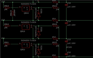
    Unfortunately I can't share the full schematic here. But I will attach an image of the balancing part.

    Thanks,

    Abhijith.

  • Hello Abhijith,

    I don't see anything wrong with the cell balancing section.

    On the damaged boards do you see any physical damage, or location where there could be current leakage of the cell balancing circuit?

    Best Regards,

    Luis Hernandez Salomon

  • Hello Luis, thanks for your continuous follow up. 

    There is no physical damage to the board or components in this section. Just that we have observed that the components associated with the balancing section of the cells that reached 0V get extremely hot to touch. We lack the tools to accurately measure this, but with the current setup we see that these components are at 70C while others are at 30C.  

    From what we understand, the AFE enables the MOSFET and will cause the cell to discharge through the bleed resistor. So the MOSFET getting damaged means the cell will keep discharging through the bleed resistor. What could be the reason for this to occur? Maybe with this approach we'll be able to better understand the cause.

    Thanks,

    Abhijith

  • Hello Abhijith,

    In the damaged boards, if the AFE is replaced, is there still an issue with the components becoming hot?

    Yes, you're correct, if the MOSFET were to get damaged, it could keep discharging the battery through the bleed resistor. Are the FETs confirmed damaged?

    Can you also share a schematic showing all of the cell balancing circuitry for the part?

    Beast Regards,

    Luis Hernandez Salomon

  • Yes, the components still remain hot. But with the AFE and all the balancing components when replaced, the board works fine.

    Do you have any thoughts on what could cause the FETs to get damaged? Only the FETs of the Cell Group 2 were damaged.

    Here's the image of the AFE.

  • Hello Abhijith,

    We did notice something, the FET that you are using has a maximum drain-source voltage of 8-V and a maximum gate-source of 5-V.

    We typically use balancing FETs that have a 50-V drain-source and 8-V gate-source absolute max. Which gives a lot of room for the FET to operate correctly.

    If the ABS max is exceed the FETs can break, as to why this could've happened, it is difficult to diagnose. If an ESD strike could reach there, it could be possible that the FETs could get damaged, or possibly in events of large transients.

    I notice that you may have Vss/GND connected directly to BAT-. Does your design have a high current path for the battery current? We typically recommend using a net-tie to connect Vss to BAT- to separate the high battery currents from the IC ground. Additionally this provides a better path for ESD strikes to flow into the battery and not into any sensitive components. Can you confirm this?

    Best Regards,

    Luis Hernandez Salomon

  • Hey, thanks for pointing that out. I will look into these FETs. Can you also check on the diodes on the same line?

    We actually have another board with the high power MOSFETs to take care of battery currents. It's like a daughter board. We have taken care of this.

    Thanks a lot, Luis.

  • Hello Abhijith,

    The Zener diodes should be okay to leave as is.

    Ok! I just wanted to confirm that was the case. Replacing the FETs with ones that have a larger drain-source abs max would be ideal.

    Best Regards,

    Luis Hernandez Salomon