This thread has been locked.

If you have a related question, please click the "Ask a related question" button in the top right corner. The newly created question will be automatically linked to this question.

TPS563207: Ripple at lower frequency

Part Number: TPS563207

Hi Team

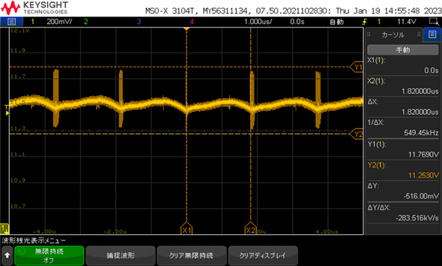
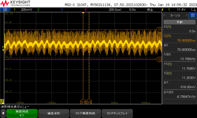
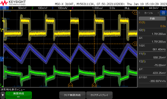
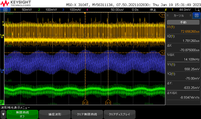
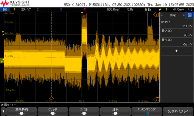
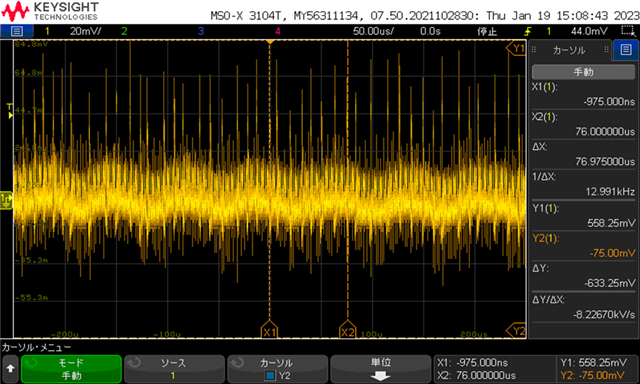
I've been testing a 12V - 3.8V application with TPS563207, and have observed some low frequency ripples at the output as below.

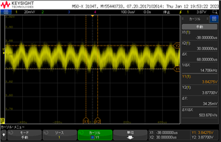
The switching frequency was at 500kHz( Ripple at switching frequency also exists, in the waveform of the oscilloscope it appears as spurs but if to scale up it can be seen clearly), while the noise frequency was around 15kHz. This low frequency noise has generated an audible noise on the inductor windings, which is a hard to ignore issue. 

I thing it might be caused by ESR of the capacitor and tried to replace the ceramic capacitor with lower ESR, but nothing changed so far, adding output caps also didn't make significant improvement to the issue. I can think of other solutions such like adding ferrite or adding a LC filter to the output, but both of these would take more board size.

Is there any other reason that could have caused this low frequency noise? Is there any other way to solve this issue?

Regards

  • Hi David,

    My colleague will give you reply next week!

    BTW, could you please share the schematic, layout and loading condition of customer application?

    Could you please help to capture waveforms of Vout, SW and IL in the same graph?

    BRs

    Zixu

  • Hi Zixu

    Thanks for the response!

    I'm checking with the customer to get the waveform you requested.

    In the meanwhile, do you know any possible reason that could have caused this issue?

    Any exist case similar to this one?(A ripple much lower than the switching frequency)

    I'm looking at external noise, input noise, high output ESR, improper layout might have caused the issue.

    Regards

  • Hi David

    It might be unstable. You could change the inductor and capacitor.

    Hope this helps.

    BR

    Ruby

  • Hi Ruby

    Could you share some insights to the waveform below?

    The noise seems to exist at Vin as well.

    Vin

    SW voltage(Y) + inductor current(B) + output voltage(G)

    FB voltage

    Regards

  • Hi David

    What is the input of the device? Did customer use DC source to test? Would you please share the schematic and layout?

    I will check firstly if the converter works stably. Then check whether there is any noise caused by layout. Could you find if the noise comes from the inductor of the capacitor? If it comes from the inductor, change to another inductor with different value (higher is preferred). If it comes from the capacitor, add Cout and try again. Or there is antinoise cap in Muruta. 

    Hope this helps.

    BR
    Ruby